
Adampower
![]()

| Step Accuracy: | ±5% | Resistance Accuracy: | ±10% |
|---|---|---|---|
| Inductance Accuracy: | ±20% | Temperature Rise: | 80°C MAX |
| Ambient Temperature Range: | -20°C~ 50°C | Storage Temperature Range: | -30°C~ 60°C |
| Insulation Resistance: | 100M Ω MIN. 500V DC | Dielectric Strength: | 500V AC 1min |
| Radial Play: | 0.02mm MAX. (450g Load) | End Play: | 0.08mm MAX. (450g Load) |
| Max. Radial Force: | 20N | Max. Axial Force: | 2N |
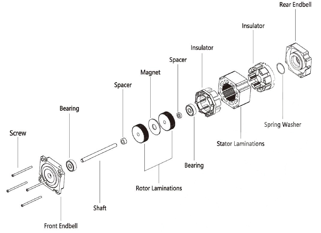
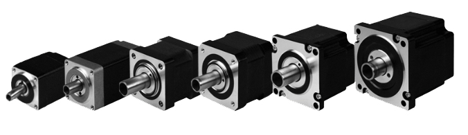
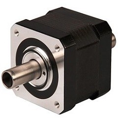
NEMA17 Hollow Shaft Stepper Motor
Electrical Specifications:
Model No. | Step Angle | Motor Length (mm) | Rated voltage (v) | Rated Current (A) | Phase Resistance (Ω) | Phase Indutance (Mh) | Holding Torque(MIN) N.cm | Weight (KG) | Inertia (g*cm2) |
| 17HS1235 | 1.8 | 35 | 3.8 | 1.2 | 2.1 | 4.2 | 7 | 0.24 | 35 |
| 17HS2049 | 1.8 | 49 | 2.5 | 2.0 | 1.35 | 3.2 | 48 | 0.36 | 77 |
Mechanical Dimensions and Wiring Diagram: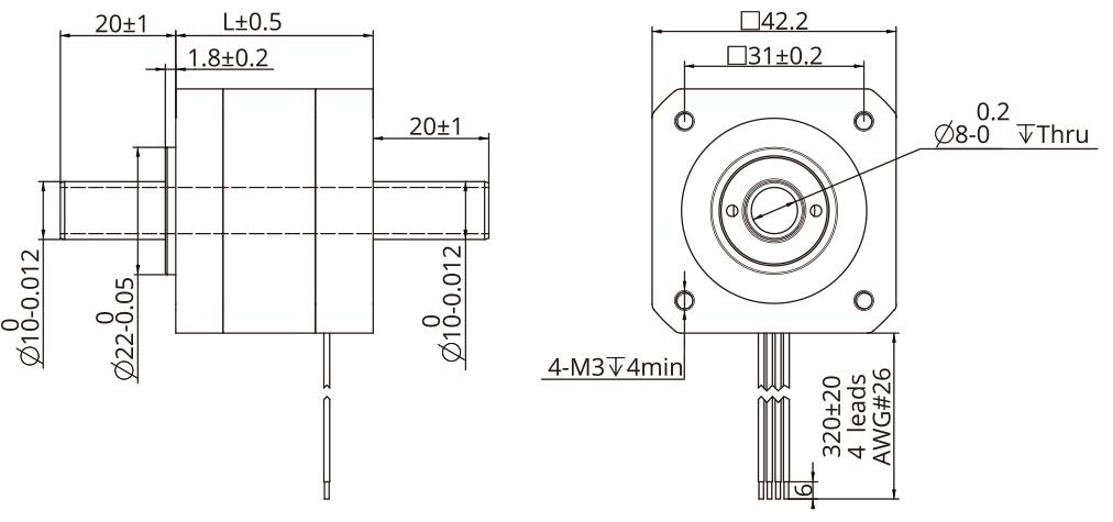
Torque Performance Curve: 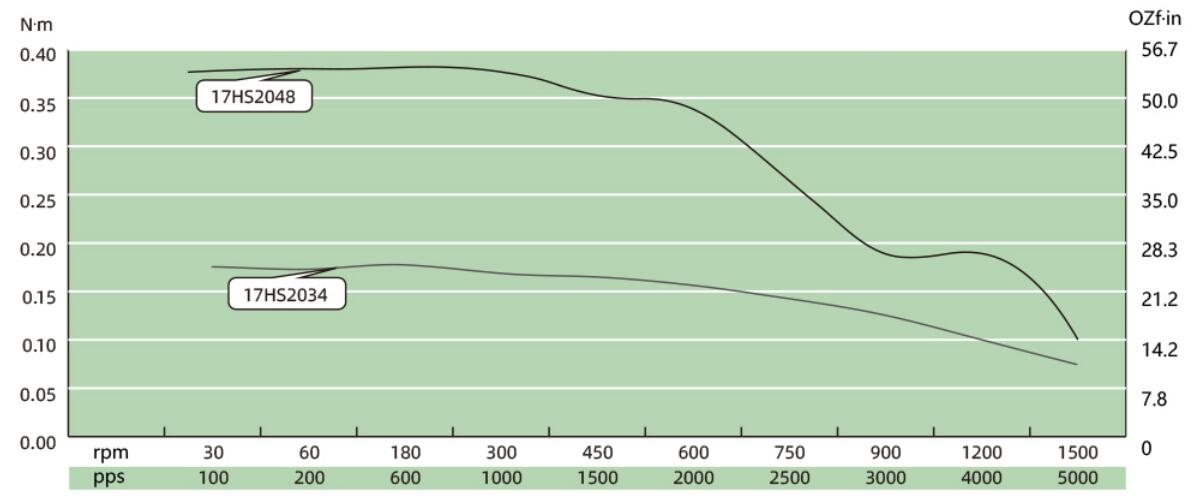
Lead Wire Mode Options:
More Information on detail, please feel free to contact me 

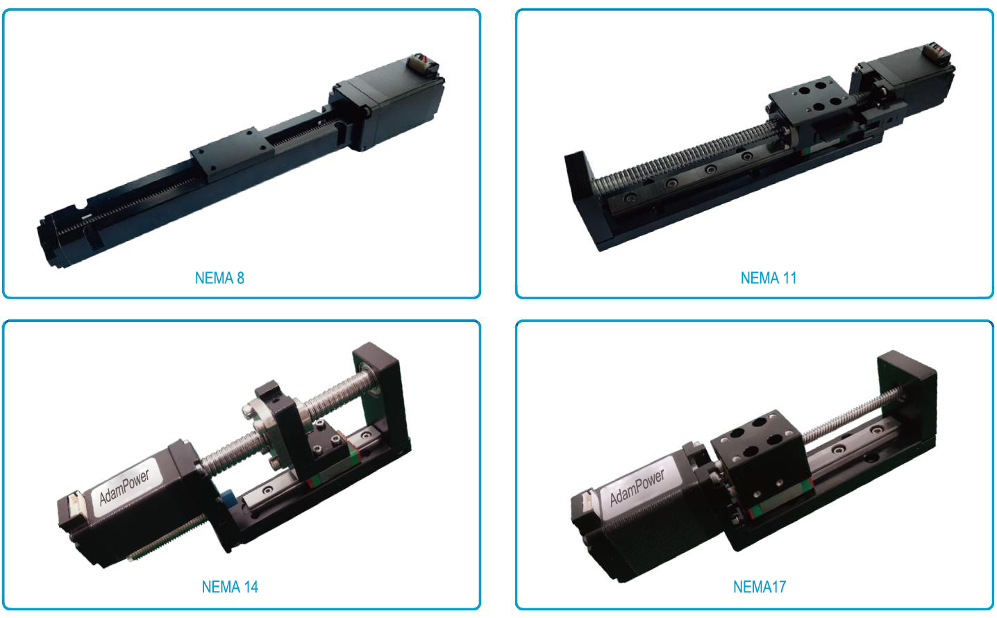
KK Series Linear Module with guide and ball screw, steel linear module,
standard or customized requirement please contact sales us directly for confirmation.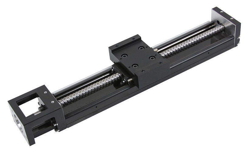
1. Ball Screw Lead:
KK30, ball screw lead: 1mm
KK40, ball screw lead: 1mm
KK50, ball screw lead: 2mm
KK60, ball screw lead: 5, 10mm
KK80, ball screw lead: 10, 20mm
KK86, ball screw lead: 10, 20mm
KK100, ball screw lead: 20mm
KK130, ball screw lead: 25mm
2. Accuracy class: General, Precise.
3. With limit switch or not
Limt switch: Omron EE-SX671, EE-SX674,
Limt switch: Panasonic GX-F12A, GX-F12A-P
4.Cover Type: Aluminum or Telescopic
5. Special requirement for the working Load, amounting flange, motors and so on.
KK30 series linear module parameter: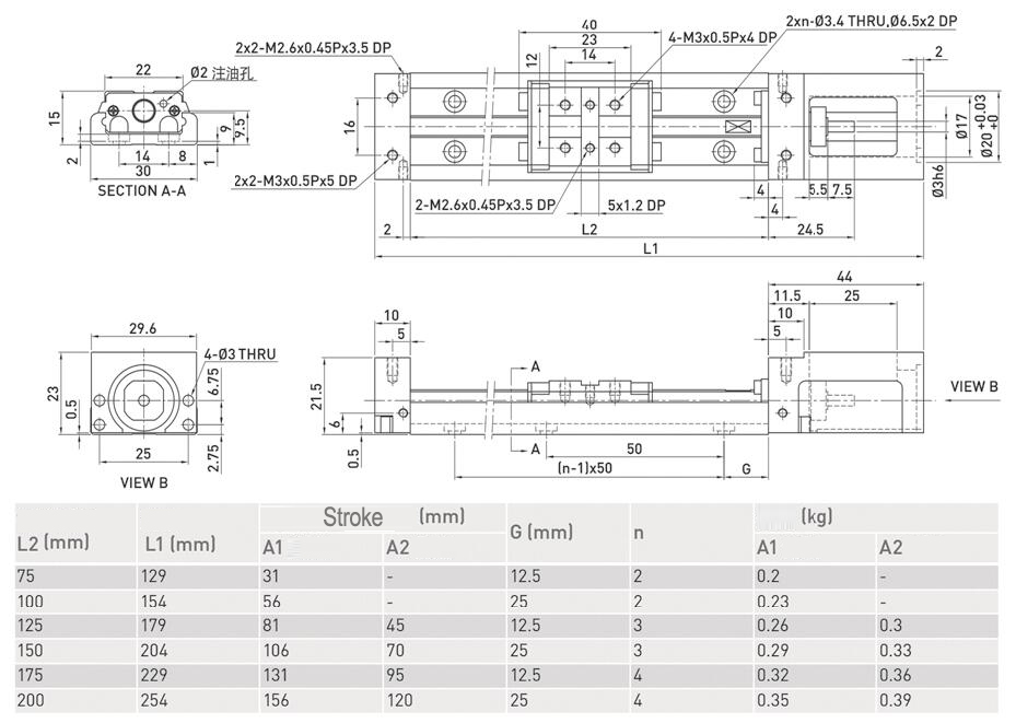
KK40 series linear module parameter: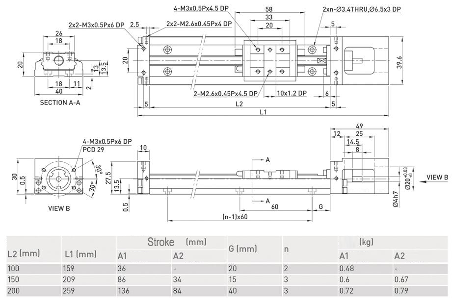
KK50 series linear module parameter: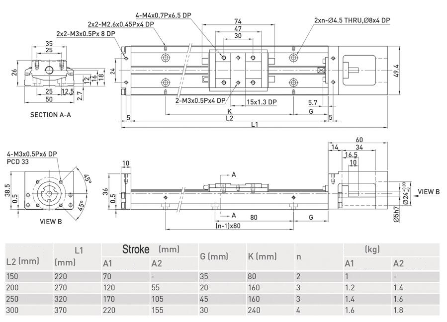
KK60 series linear module parameter: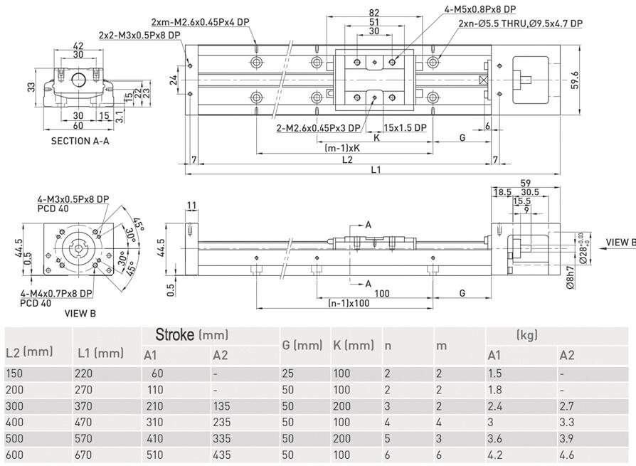
KK80 series linear module parameter: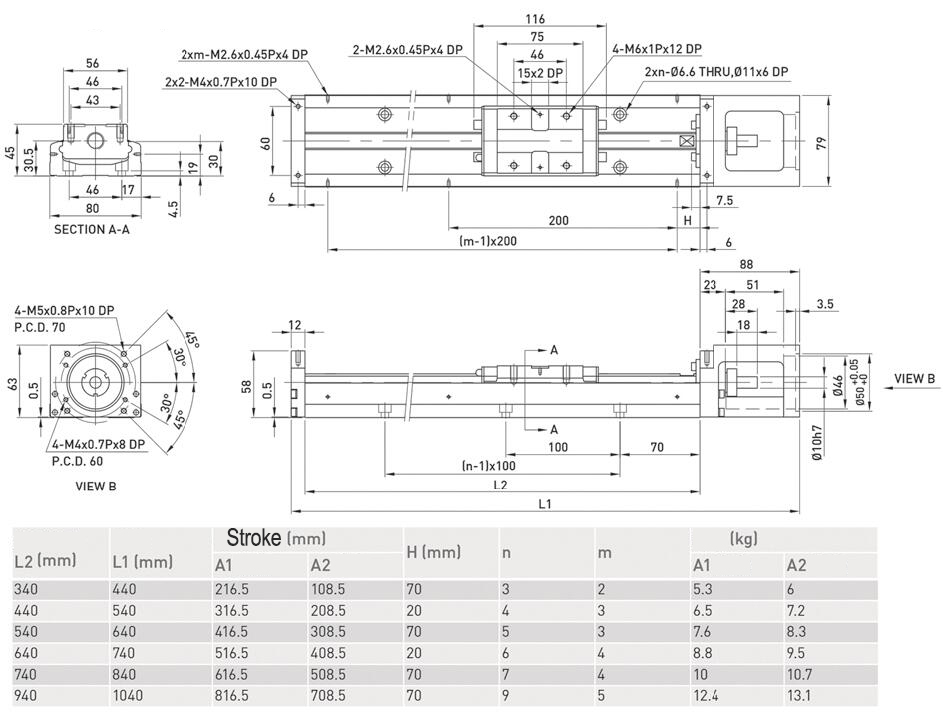
KK86 series linear module parameter: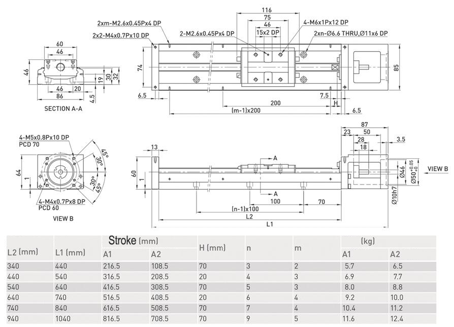
KK100 series linear module parameter: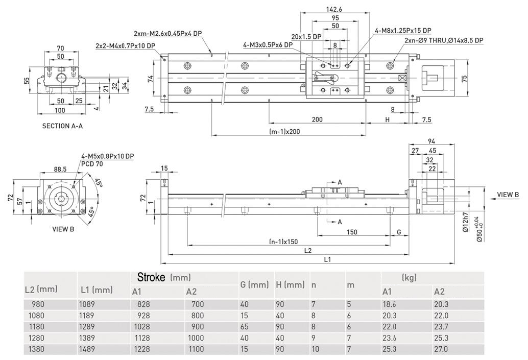
KK130 series linear module parameter: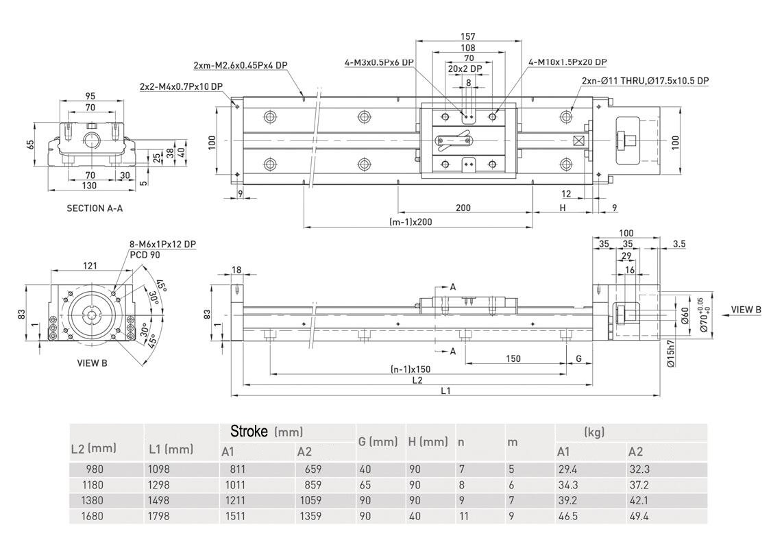
More Information on detail, please feel free to contact me

CANopen Stepper Motor Controller, It supports the CiA301 and CiA402 sub-protocols
of the CANopen protocol.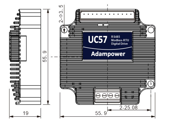
UC57 uses the latest 32-bit DSP digital chip and has advanced drive control algorithms and noise
suppression technology to ensure smooth motor operation. Stable, low noise, and temperature controllable.
Users can set any ID address within 1-255 and any current value within 0-8A through the host computer.
Maximum output peak current of the UC42 bus driver is 5.6A.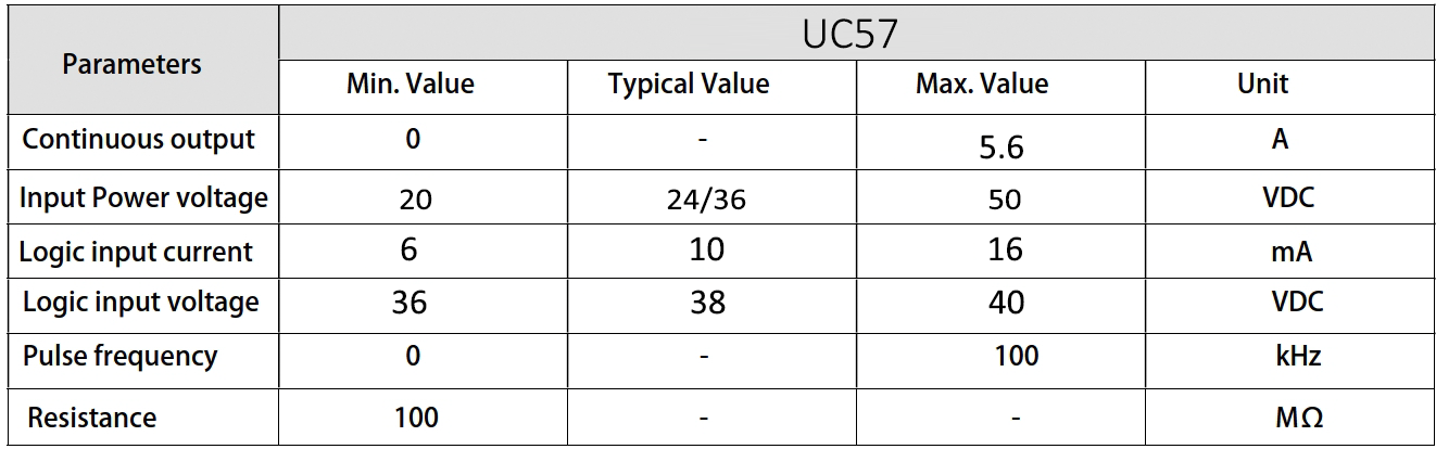
UC57 can be set to 1-256 subdivisions and adopts built-in micro-subdivision technology, which can achieve
high subdivision effects even under low subdivision conditions, ensuring that the motor operates with uniform
step intervals and no large or small step problems.
3 input signal ports and 2 output signal ports, supporting position, speed, and return-to-origin control modes.
with highest communication rate in 1Mbps.
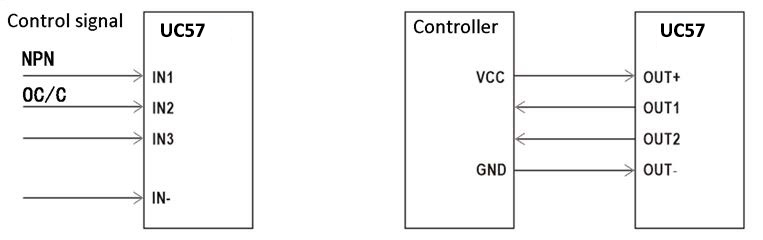
Input signal Wiring diagram and Output Signal wiring diagram↑
UC57 is designed for NEMA23 stepper motor, we supply NEMA23 integrated stepper motor with 1000 line Magnetic Encoder
And 1000 line ABZ signal Optoelectronic encoder:
Holding Torque: 1.0, 2.0, 3.0Nm
If just choose UC23 stepper motor controller with requirement for low vibration, please inform us for
setting parameters before sale. 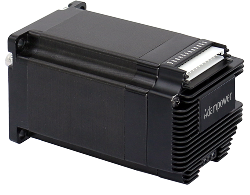
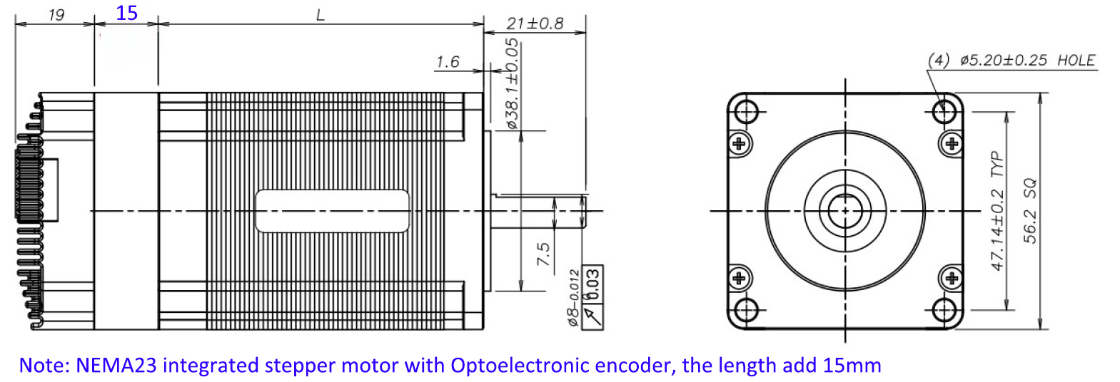
| Model No. | Holding Torqure(Nm) | Motor Length(mm) | overall length(mm) | Encoder |
| UC5710IEC | 1.0 | 56 | 75 | 1000 line Magnetic Encoder |
| UC5720IEC | 2.0 | 76 | 95 | |
| UC5730IEC | 3.0 | 90 | 109 | |
| UC5710IEP | 1.0 | 56 | 90 | 1000 line ABZ Optoelectronic encoder |
| UC5720IEP | 2.0 | 76 | 105 | |
| UC5730IEP | 3.0 | 90 | 124 |
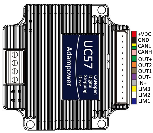
Port Definition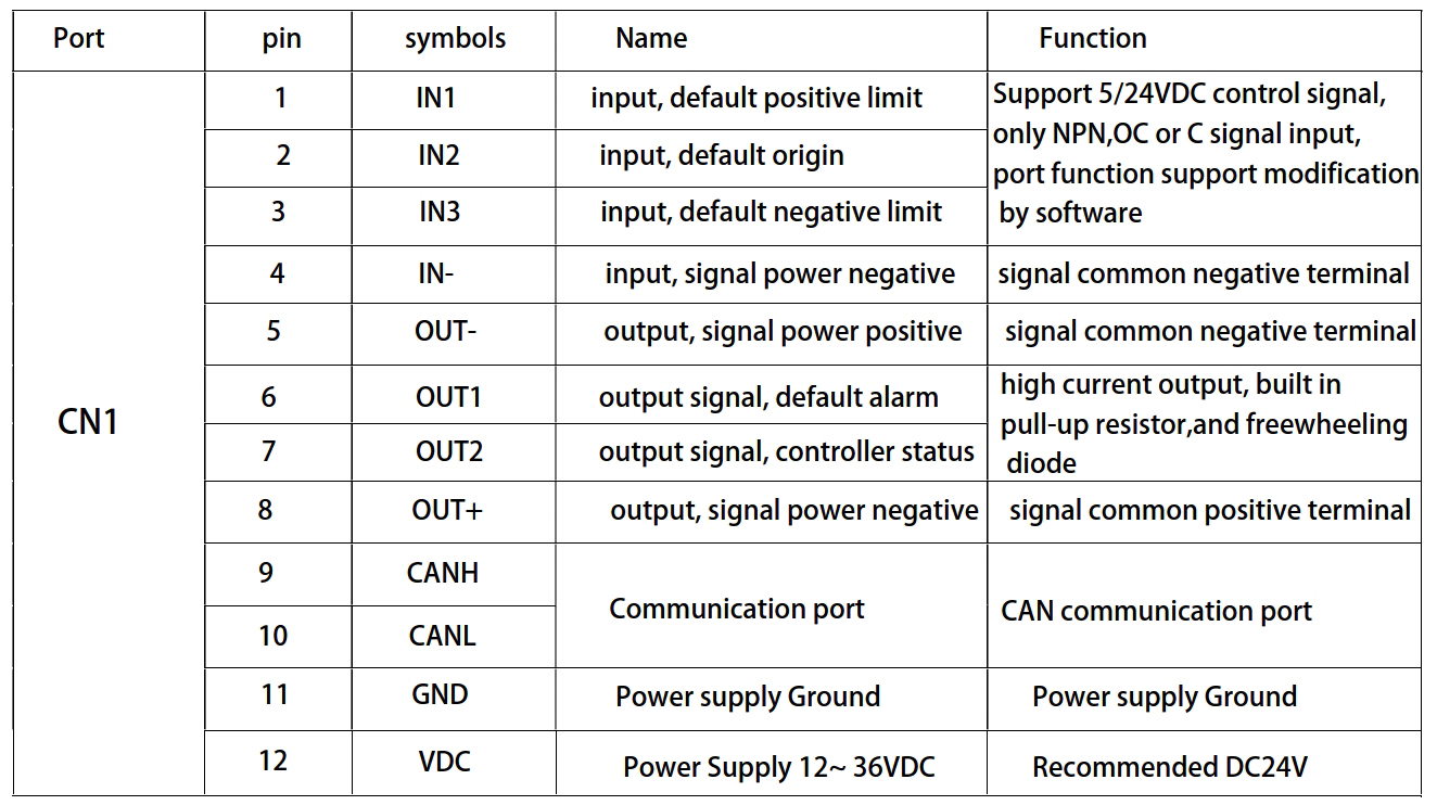
It can be connected to PLC, industrial computer, controller and other host computers with only two
communication lines. Through the built-in motion Control instructions can realize a network of up to
100-axis stepper motors.
especially suitable for long-distance multi-axis applications, which can reduce wiring and enhance
the reliability of drive operation.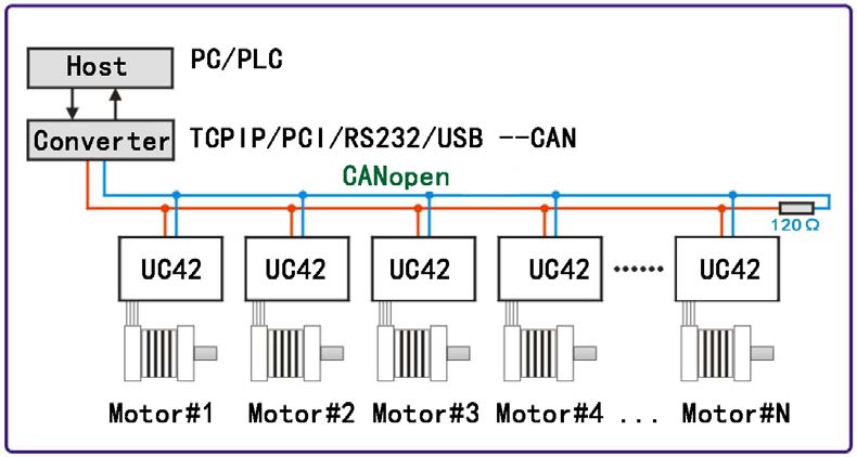
Mainly used in electronic equipment, semiconductors, medical instruments, environmental protection equipment,
automatic detection equipment, small automatic processing equipment and other automation equipment with
multiple motor shaft applications and compact requirements for equipment space
CANopen Command Read and Write: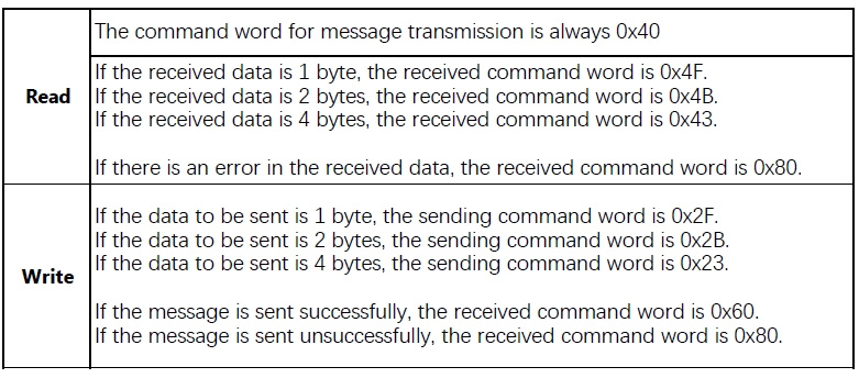
UC57 CANopen Stepper Motor Controller User Manual 
CANOpen Software
More Information on detail, please feel free to contact me

| Step Accuracy: | ±5% | Resistance Accuracy: | ±10% |
|---|---|---|---|
| Inductance Accuracy: | ±20% | Temperature Rise: | 80°C MAX |
| Ambient Temperature Range: | -20°C~ 50°C | Storage Temperature Range: | -30°C~ 60°C |
| Insulation Resistance: | 100M Ω MIN. 500V DC | Dielectric Strength: | 500V AC 1min |
| Radial Play: | 0.02mm MAX. (450g Load) | End Play: | 0.08mm MAX. (450g Load) |
| Max. Radial Force: | 20N | Max. Axial Force: | 2N |
NEMA34 Hollow Shaft Stepper Motor
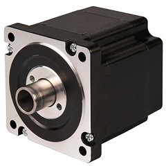
Electrical Specifications:
Model No. | Step Angle | Motor Length (mm) | Rated Current (A) | Phase Resistance (Ω) | Phase Indutance (Mh) | Holding Torque(MIN) N.m | Rated Voltage v | Detent Torque (N.m) |
| 34HS2076 | 1.8 | 76.0 | 3.0 | 1.9 | 19 | 4.5 | 5.7 | 0.095 |
Mechanical Dimensions and Wiring Diagram: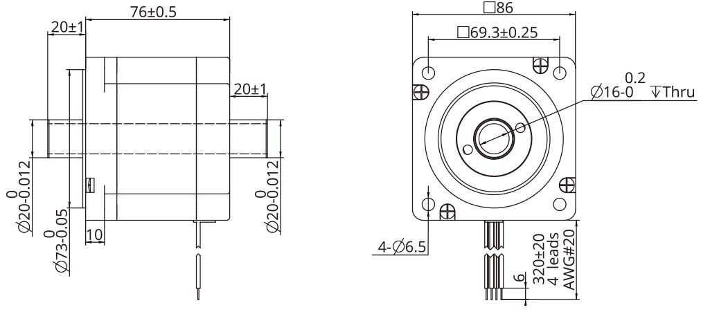
Torque Performance Curve: 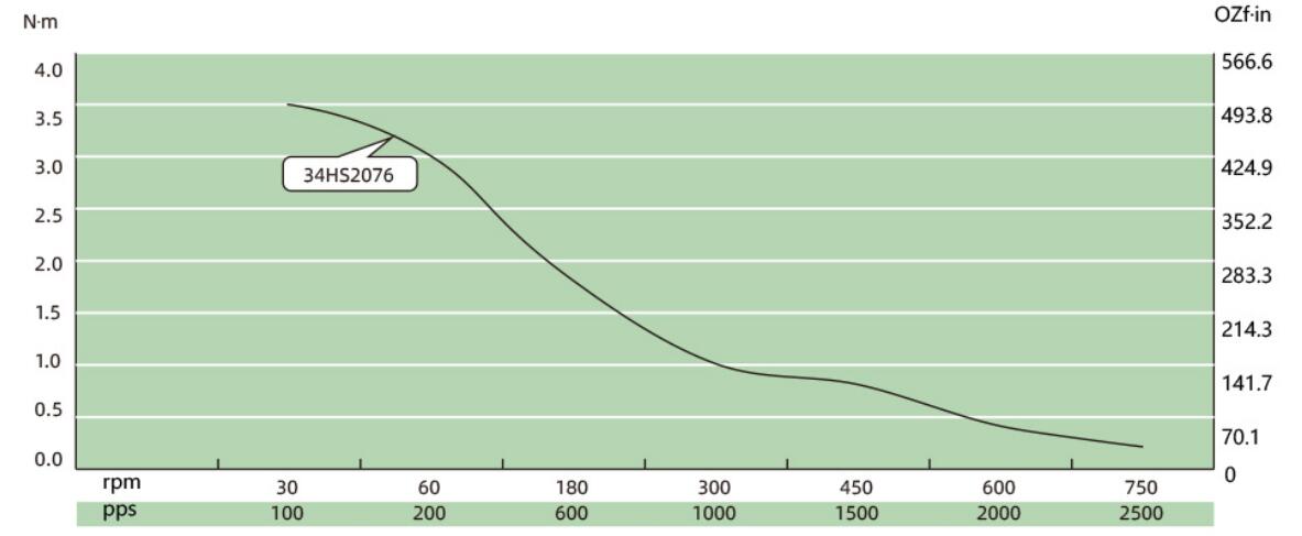
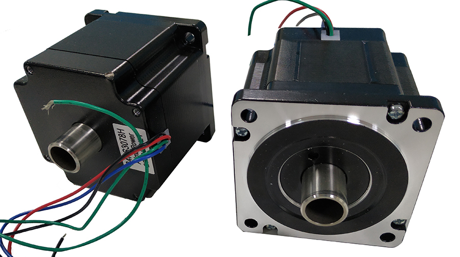
Lead Wire Mode Options:
More Information on detail, please feel free to contact me

AR57 is a high-integrated and compact size stepper driver. It adopts standard RS485 communication
protocol, can be connected with PLC, HMI, industrial computer and other upper computer with only two
communication lines. Up to 32 axes of motion platform networking can be achieved with its built-in motion
control commands.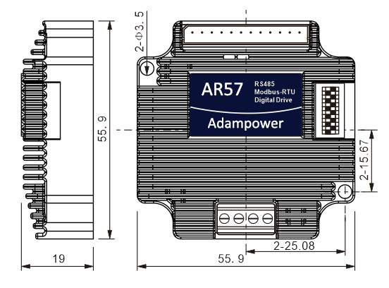
AR57 can be set to 1-256 subdivisions and adopts built-in micro-subdivision technology, which can achieve
high subdivision effects even under low subdivision conditions, ensuring that the motor operates with uniform
step intervals and no large or small step problems.
Can be set between 1-256 subdivisions, with uniform motor step spacing; Stable output at 1/12 rpm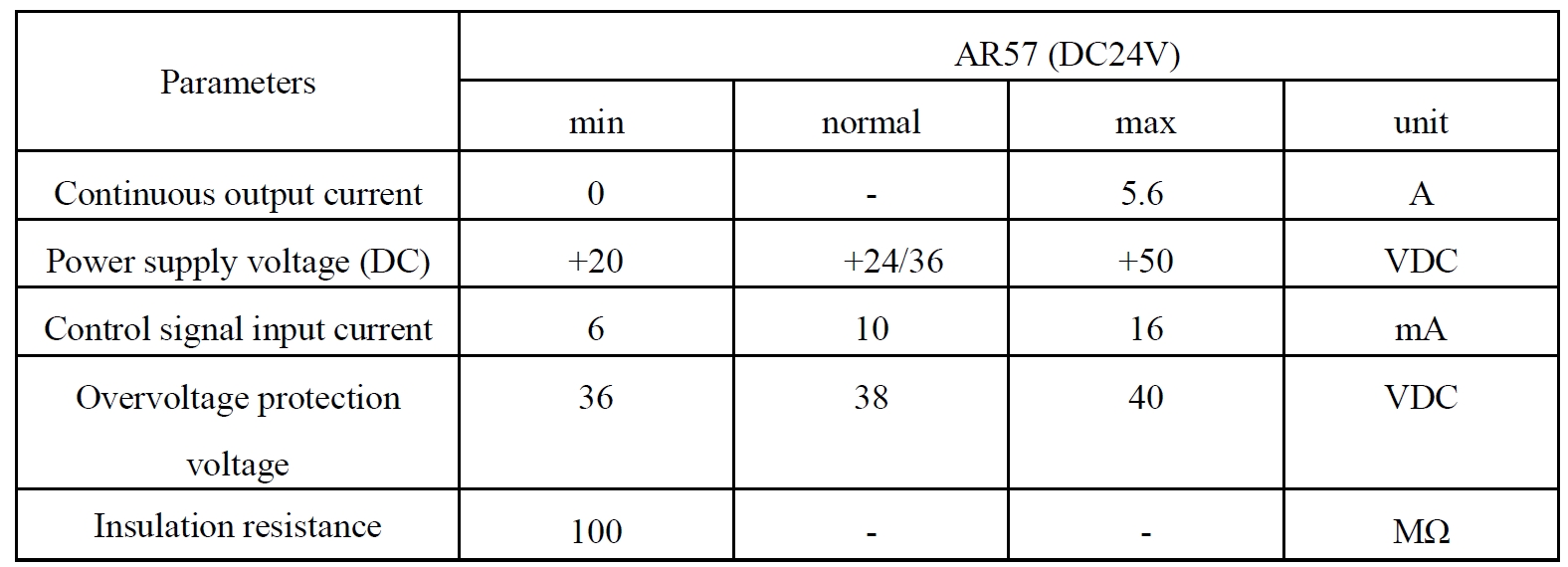
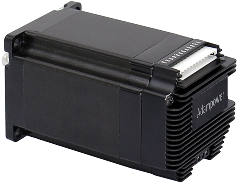
AR57 is designed for NEMA23/NEMA24 stepper motor, The NEMA23/NEMA24 integrated stepper motor with
torque 1.0, 2.0 and 3.0Nm:
| Model No. | Holding Torque(Nm) | Motor Length(mm) | Encoder Type |
| AR57-10 | 1.0 | 57-56 | 1000 line Encoder, Magnetic or Optoelectronic |
| AR57-20 | 2.0 | 57-76 | |
| AR57-30 | 3.0 | 60-90 |
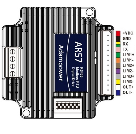
Port Definition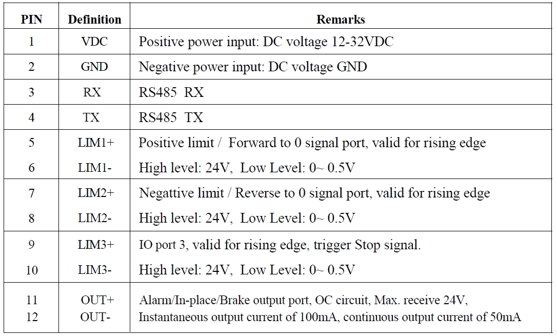
OUT /OUT- as defferential output port, Max.receive voltage is DC24V, and instaneous ouput
current is 100mA, continuous output current is 50mA.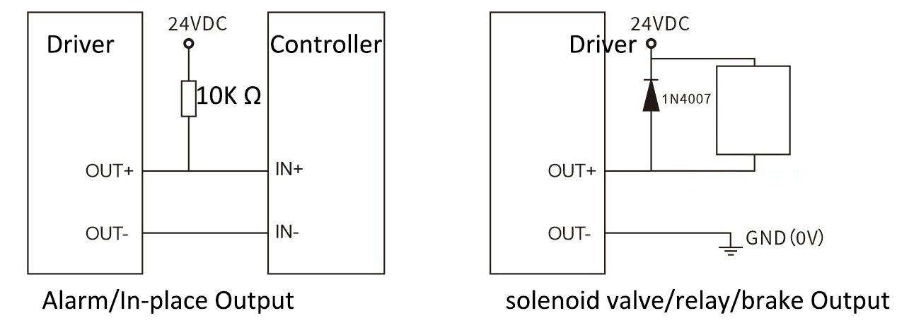
Set ID address, Baud Rate and Ouptut current by SW1~SW10: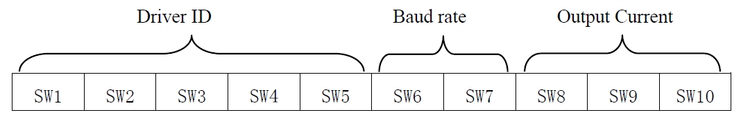
Set ID address:

Note: The formula for calculating the ID table is: ID=1*SW1 2*SW2 4*SW3 8*SW4 16*SW5.
The default ID is 0, 0 means broadcast address for global control
Set Baud Rate:
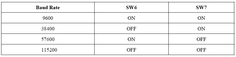
Note: When the communication baud rate in the table cannot meet the usage requirements, the baud rate can be
customized by the host computer when SW6 and SW7 are turned ON.
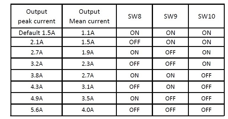
Set Output Current:
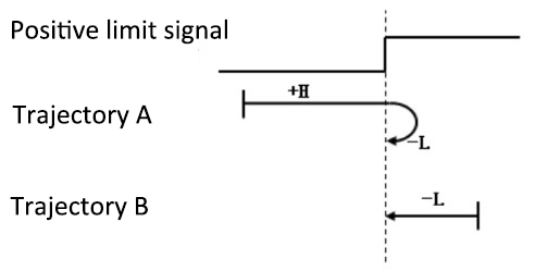
Zero-return function with two trajectory A and when limit signal is triggered and not: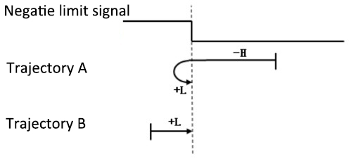
AR57 Modbus Stepper Motor Controller User Manual
Software Modbus Poll 
AdamPower Software
More Information on detail, please feel free to contact me

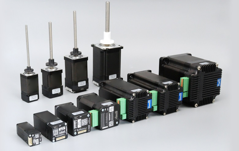
Size:
NEMA6, NEMA8, NEMA11, NEMA14, NEMA17, NEMA23, NEMA23, NEMA34
14mm, 20mm, 28mm, 35mm, 42mm, 57mm, 60mm, 86mm
Stepper
0.001524mm~0.16mm
Performance
Maximum thrust up to 240kg, low temperature rise, low vibration, low noise,
long life (up to 5 million cycles), and high positioning accuracy (up to ±0.005 mm)
Application
Medical diagnostic equipment, life science instruments, robots, optical equipment,
analytical instruments, semiconductor equipment, communication equipment, automation equipment
NEMA6 Lead Screw Linear Actuators
Linear Module, Linear Slider
| Motor Type | Bipolar stepper |
| Step Angle | 1.8° |
| Voltage (V) | 2.5 / 6.3 |
| Current (A) | 0.5 |
| Resistance (Ohms) | 5.1 / 12.5 |
| Inductance (mH) | 1.5 / 4.5 |
| Lead Wires | 4 |
| Motor Length (mm) | 30 / 42 |
| Stroke (mm) | 30 / 60 / 90 |
| Ambient Temperature | -20℃ ~ 50℃ |
| Temperature Rise | 80K Max. |
| Dielectric Strength | 1mA Max. @ 500V, 1KHz, 1Sec. |
| Insulation Resistance | 100MΩ Min. @500Vdc |
Motor Characteristics:
| Motor | Phase voltage [V] | Phase Current [A] | Phase Resistance [Ω] | Phase Inductance [mH] | Lenght [mm] | Number of lead Wires | Weight [g] |
|---|---|---|---|---|---|---|---|
| 0632 | 6.6 | 0.3 | 22 | 4.5 | 32 | 4 | 60 |
Available Lead Screw and Travel per Step:
Diameter (mm) | Lead (mm) | Step (mm) |
3.5 | 0.3048 | 0.001524 |
3.5 | 0.6096 | 0.003048 |
3.5 | 1 | 0.005 |
3.5 | 1.2192 | 0.006096 |
3.5 | 2 | 0.01 |
3.5 | 4 | 0.02 |
3.5 | 8 | 0.04 |
3.5 | Customized size | |
NEMA6 Linear Actuator outline drawing:
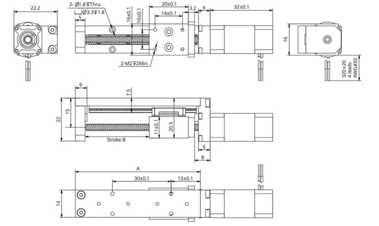
| Stroke B (mm) | 20 | 40 | 60 | 80 | 100 | 120 | 150 | Size can be Customized |
| Dimension A (mm) | 60 | 80 | 100 | 120 | 140 | 160 | 190 |
More Information on detail, please feel free to contact me

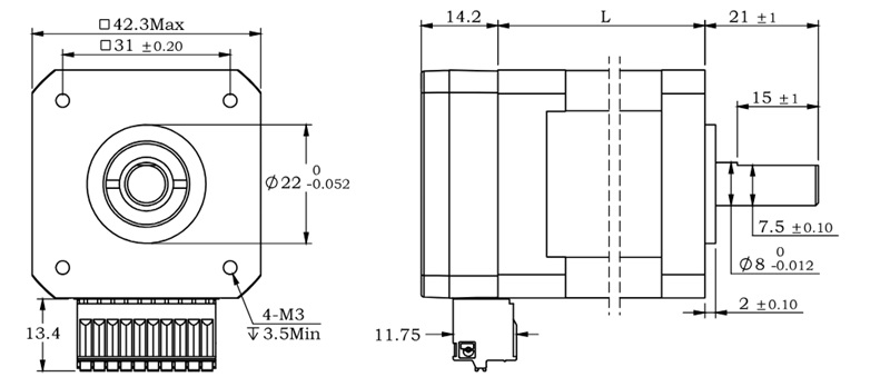
The IS17A series integrated motor is the perfect combination of drive and stepper motor,
which perfectly integrates stepper motor and drive technology, also built in a battery free
1023 turn mechanical absolute value encoder, it can save installation space,
Simultaneously saving design and production costs, supporting RS485 instruction control.
| Item | Specifications |
| Stepper Motor Size | NEMA17 |
| Encoder type | 1023 ring absolute encoder |
| Working voltage | 8-50VDC, Recommend DC36V |
| Driver Current | 0.2-3.2A |
| Velocity range | Up to 3000RPM |
| Control Method | RS485 √ Pulse& Direction, Twin-Pulse, I/O, Built-in Program |
| Torque value | 0.2 - 0.6Nm |
| Nonvolatile storage | Configuration parameters are stored in FLASH inside the MCU |
| DI and DO | 2 DI, 1 DO |
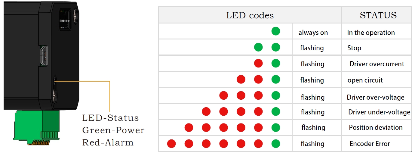
| Protection | Overvoltage, undervoltage, overcurrent, open winding, position deviation |
| Digital Input (2) | Receive 3.3-24VDC | ||
| Digital Output(1) | Maximum withstand voltage of 30V, | ||
| Maximum input or output current 30mA | |||
| Accuracy | 4000 pulses/r | ||
Motor Parameters
| Model No. | length mm L | Shaft length mm | Shaft dia. mm | Phase current A | Resistance Ω | inductance mH | Hold torque N.m | Inertia g.cm² | Weight g |
| IS1704 | 64 | 24 | 5 | 2.0 | 2.0 | 4.2 | 0.4 | 57 | 380 |
| IS1705 | 72 | 24 | 5 | 2.0 | 1.3 | 2.9 | 0.5 | 82 | 460 |
| IS1706 | 84 | 24 | 5 | 2.5 | 1.3 | 3.2 | 0.6 | 116 | 700 |
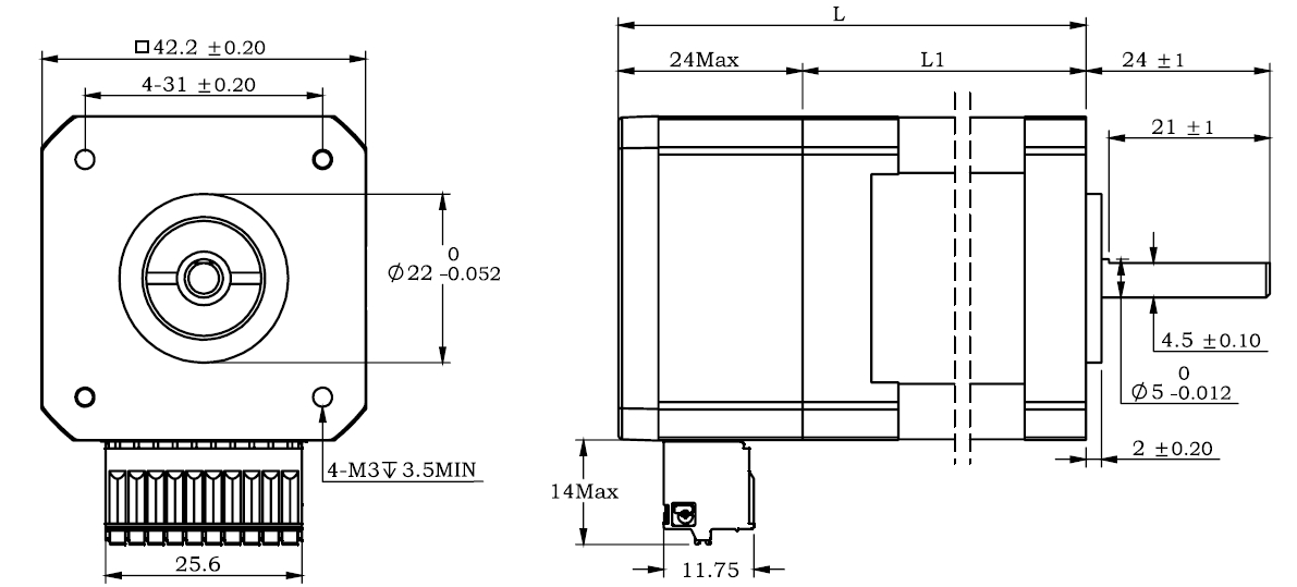
Wiring Diagram: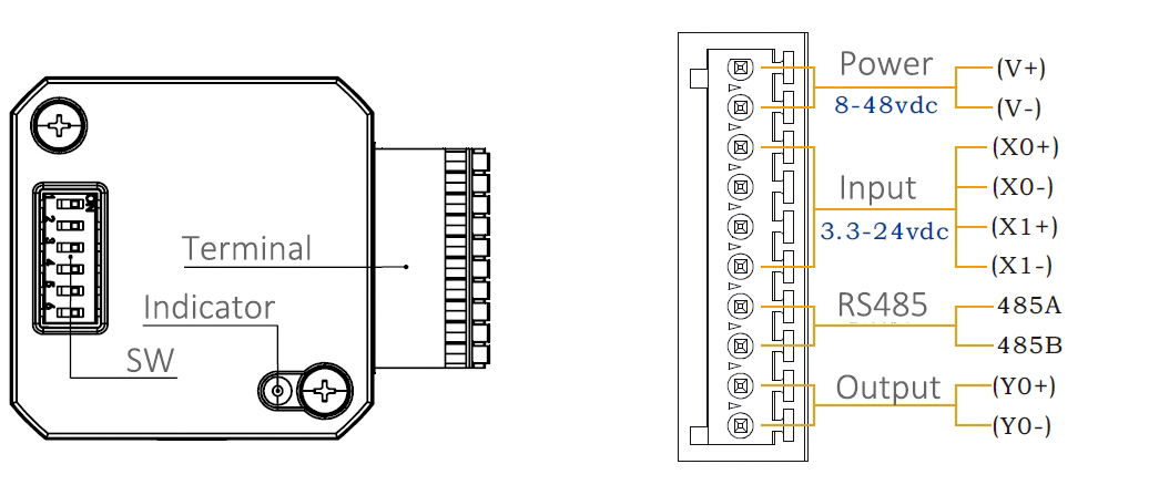
Terminal Definition
| Terminal | Name | Description | |
| 1 | V | 8-48VDC | |
| 2 | V- | GND | |
| 3 | X0 (PU ) | Optoelectronic isolation, differential, High level can directly receive 3.3-24VDC, with a minimum pulse width of 2us, The maximum pulse frequency is 400KHz, which can be used as a universal input port or a high-speed pulse input port | |
| 4 | X0-(PU-) | ||
| 5 | X1 (DR ) | ||
| 6 | X1-(DR-) | ||
| 7 | 485A(EN ) | RS485 Communication port, default baud rate is 115200, | |
| 8 | 485B(EN-) | ||
| 9 | Y0 (AL ) | The default alarm output port can detect the driver alarm status and provide feedback to the main station. Other functions can be set through communication | |
| 10 | Y0-(AL-) | ||
Set Device ID by SW1, SW2, SW3, SW4 and SW5
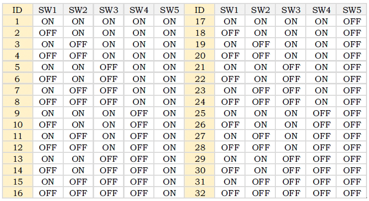
SW6 is used to set the terminal resistance; OFF=0 ohms; ON=120 ohms
Block Diagram:
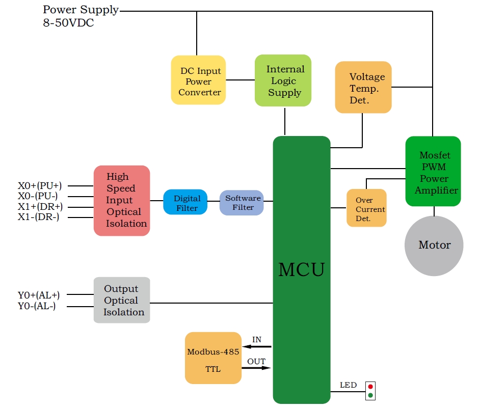
2 Input signals can directly receive 3.3-24V DC levels at high levels, Max. frequency of 400KHZ.
X0: pulse input, IO start/stop, limit, direction, universal input.
X1 pulse input, IO start/stop, limit, direction, universal input.
1 Output signal, maximum withstand voltage 30V, maximum input or output current 30mA
Y0 : alarm output, universal output, and factory default alarm output.
LED indicator and status:
CRC Check routine by C# :
Uint16 Funct_CRC16(unsigned char * puchMsg, Uint16 DataLen)
{
Uint16 i,j,tmp;
Uint16 crcdata=0xFFFF;
for(i=0;i<DataLen;i )
{
crcdata=(*puchMsg)^crcdata;
puchMsg ;
for(j=0;j<8;j )
{
tmp=crcdata&0x0001;
crcdata=crcdata>>1;
if(tmp){
crcdata=crcdata^0xA001;
}
}
}
returncrcdata;
}
Software Modbus Poll
Software Step-Config
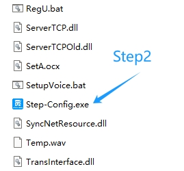
1. Extract the zip file, open CommFile and Click Step-Config.exe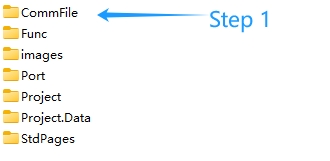
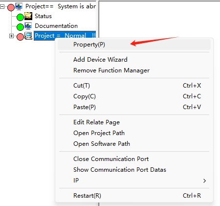
2. Right Click Modbus_485, and Click Property: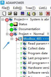
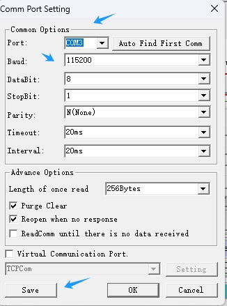
3. Click Property ComNN, Choose COM port, Baud rate and click Save and OK.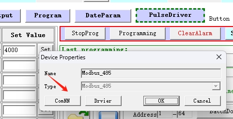
4. Start to use software control the RS485 Integrated stepper motor by below buttons: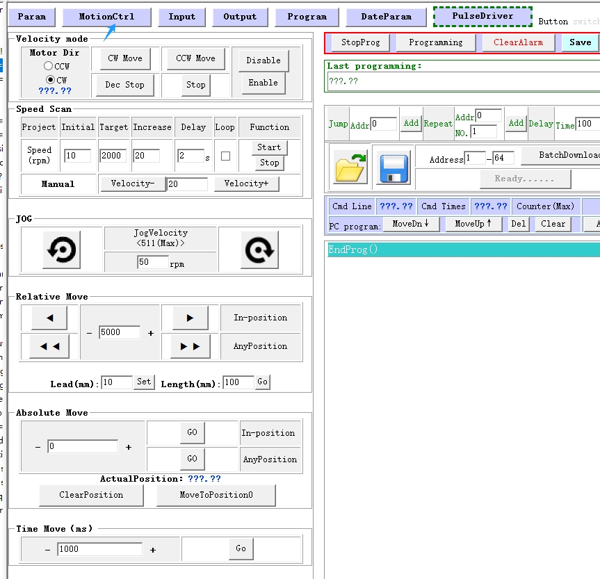
RS485 Stepper Motor Controller Manual
Block Diagram:
2 Input signals can directly receive 3.3-24V DC levels at high levels, Max. frequency of 400KHZ.
X0: pulse input, IO start/stop, limit, direction, universal input.
X1 pulse input, IO start/stop, limit, direction, universal input.
...
1 Output signal, maximum withstand voltage 30V, maximum input or output current 30mA
Y0 : alarm output, universal output, and factory default alarm output.
LED indicator and status:

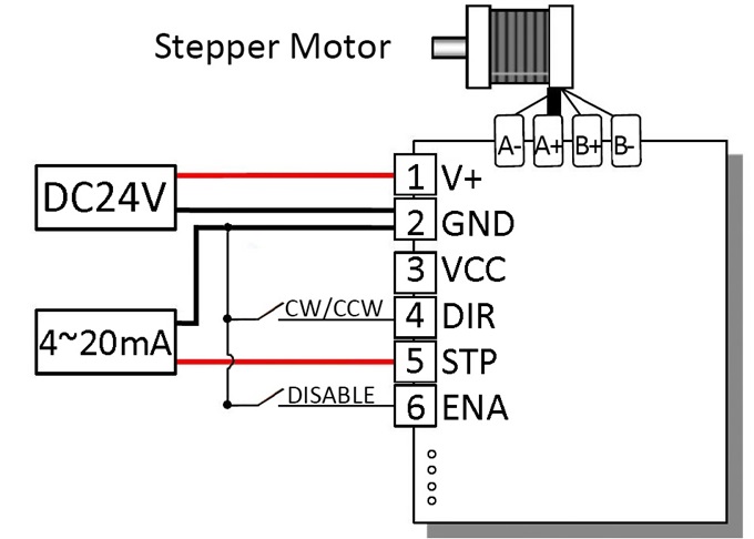
4~20 mA current-adjustable stepping motor driver
 | 420MA | |||
minimum value | Typical value | Maximum value | Unit | |
Supply Voltage (DC) | 12 | 24 | 24 | VDC |
Control Signal | 4 | 10 | 20 | mA |
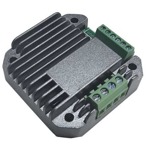
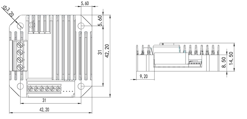
● Miniature size 42.2mmx42.2mm x14.5mm
● DC input voltage 12~40VDC, recommended working voltage 24VDC.
● Continuous output current 1.4A max, max peak current 2.0A.
● Integrated design, mounted with NEMA17, NEMA23 stepper motor.
● Low vibration, low noise, stable operation, low motor heating.
● Working Speed Range can be customized as requirmeent.
● Adjusting current: 4~20mA corrsponding Speed: 0~30RPM(defualt setting for peristaltic pumps).
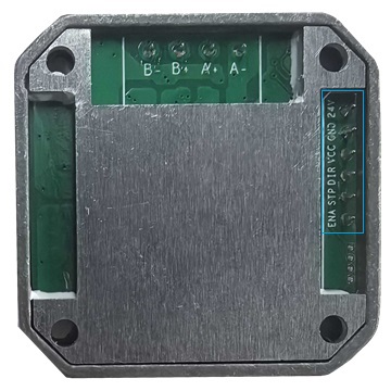
| Pin No. | Name | Description |
| 1 | 24V | Supply voltage: 12-40VDC, Recommend DC24V |
| 2 | GND | Supply Voltage Ground: GND/0V |
| 3 | VCC | Reserved; H/L Speed Option or other Customized requirement |
| 4 | DIR | The rotation direction of the motor, CW/CCW |
| 5 | STP | The postive pole of the speed-regulating current |
| 6 | ENA | Enable the Stepper Motor |
- Wiring Diagram:
Demo Video:
Customized Working Speed Range 0-300RPM for peristaltic pumps requirement.
Adjusting current: 4~20mA corrsponding Speed: 0~30RPM:
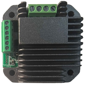
When this NEMA17 Sized Driver assembled with NEMA23 motor via a flange,
an Integrated Stepper Motor is formed:
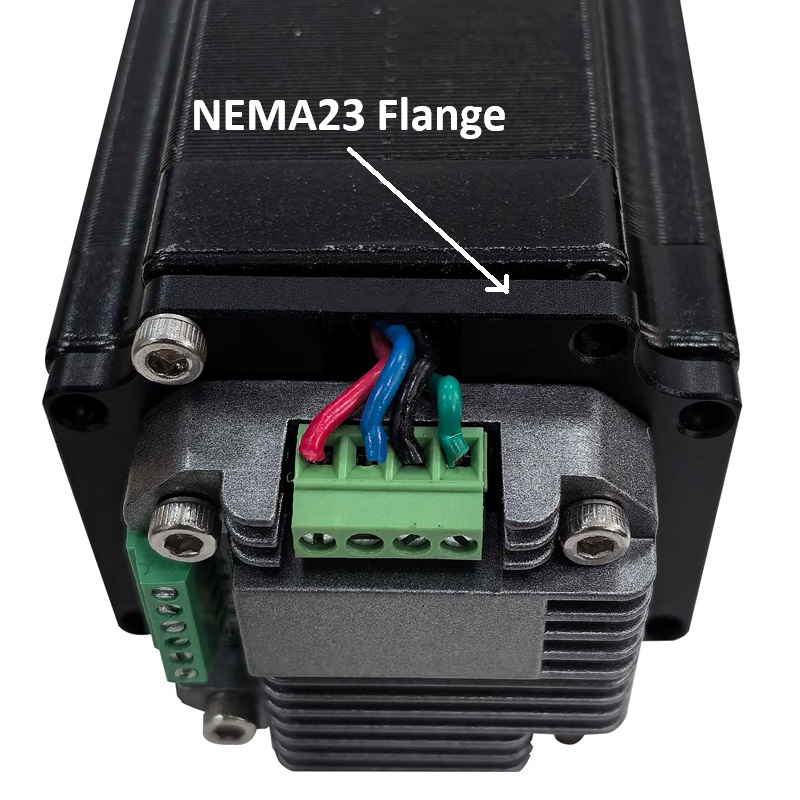
- More Information on detail, please feel free to contact me

4~20 mA current-adjustable stepping motor driver
| 420MA | |||
minimum value | Typical value | Maximum value | Unit | |
Supply Voltage (DC) | 12 | 24 | 24 | VDC |
Control Signal | 4 | 10 | 20 | mA |
● Miniature size 42.2mmx42.2mm x14.5mm
● DC input voltage 12~40VDC, recommended working voltage 24VDC.
● Continuous output current 1.4A max, max peak current 2.0A.
● Integrated design, mounted with NEMA17, NEMA23 stepper motor.
● Low vibration, low noise, stable operation, low motor heating.
● Working Speed Range can be customized as requirmeent.
● Adjusting current: 4~20mA corrsponding Speed: 0~30RPM(defualt setting for peristaltic pumps).
| Pin No. | Name | Description |
| 1 | 24V | Supply voltage: 12-40VDC, Recommend DC24V |
| 2 | GND | Supply Voltage Ground: GND/0V |
| 3 | VCC | Reserved; H/L Speed Option or other Customized requirement |
| 4 | DIR | The rotation direction of the motor, CW/CCW |
| 5 | STP | The postive pole of the speed-regulating current |
| 6 | ENA | Enable the Stepper Motor |
- Wiring Diagram:
Demo Video:
Customized Working Speed Range 0-300RPM for peristaltic pumps requirement.
Adjusting current: 4~20mA corrsponding Speed: 0~30RPM:
When this NEMA17 Sized Driver assembled with NEMA23 motor via a flange,
an Integrated Stepper Motor is formed:
- More Information on detail, please feel free to contact me

CANopen Stepper Motor Controller, It supports the CiA301 and CiA402 sub-protocols
of the CANopen protocol.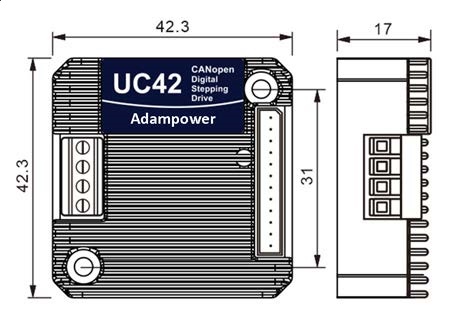
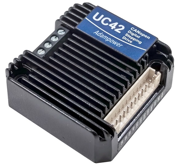
UC42 uses the latest 32-bit DSP digital chip and has advanced drive control algorithms and noise
suppression technology to ensure smooth motor operation. Stable, low noise, and temperature controllable.
Users can set any ID address within 1-255 and any current value within 0-8A through the host computer.
Maximum output peak current of the UC42 bus driver is 2.5A.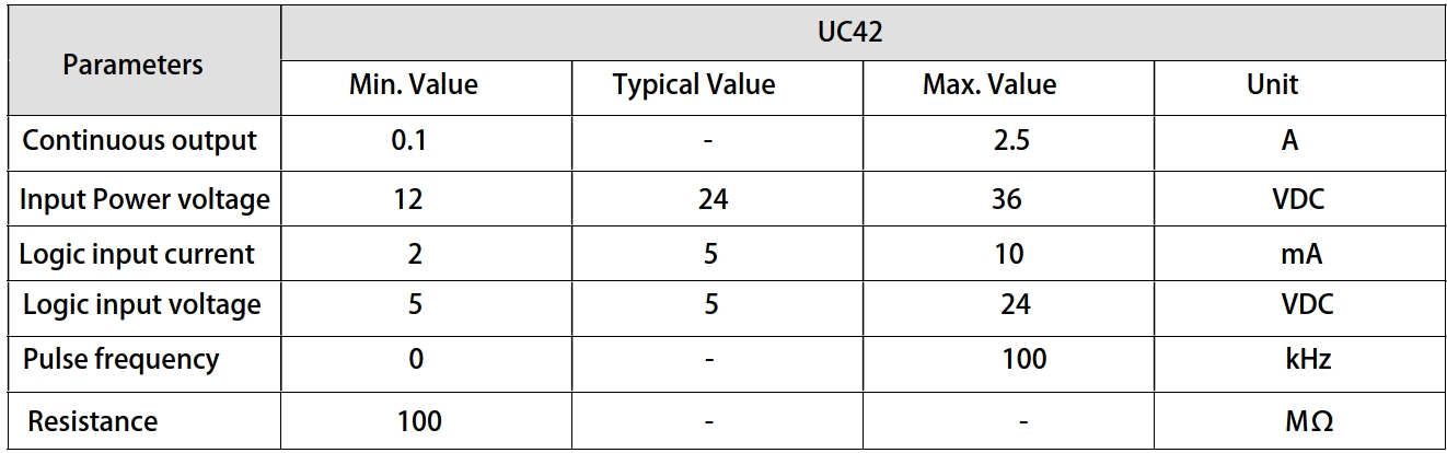
UC42 can be set to 1-256 subdivisions and adopts built-in micro-subdivision technology, which can achieve
high subdivision effects even under low subdivision conditions, ensuring that the motor operates with uniform
step intervals and no large or small step problems.
3 input signal ports and 2 output signal ports, supporting position, speed, and return-to-origin control modes.
with highest communication rate in 1Mbps.
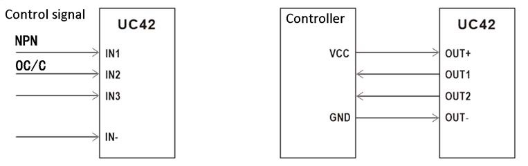
Input signal Wiring diagram and Output Signal wiring diagram↑
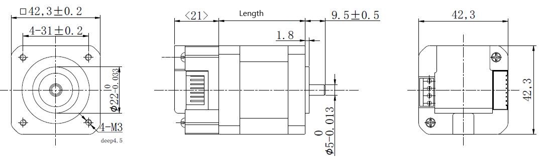
UC42 is designed for NEMA17 stepper motor, we supply NEMA17 integrated stepper motor with
torque 0.35, 0.50 and 0.7Nm:
if just choose UC42 stepper motor controller with requirement for low vibration, please inform us for
setting parameters before sale. 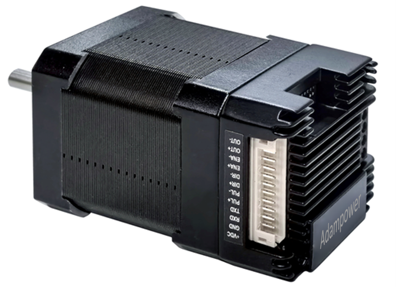
| Model No. | Holding Torqure(Nm) | Motor Length(mm) |
| UC42-03 | 0.35 | 40 |
| UC42-05 | 0.50 | 48 |
| UC42-07 | 0.70 | 60 |
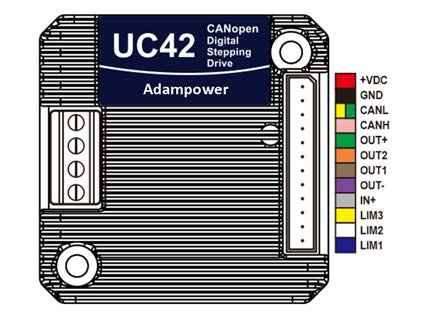
Port Definition
It can be connected to PLC, industrial computer, controller and other host computers with only two
communication lines. Through the built-in motion Control instructions can realize a network of up to
100-axis stepper motors.
especially suitable for long-distance multi-axis applications, which can reduce wiring and enhance
the reliability of drive operation.

Mainly used in electronic equipment, semiconductors, medical instruments, environmental protection equipment,
automatic detection equipment, small automatic processing equipment and other automation equipment with
multiple motor shaft applications and compact requirements for equipment space
CANopen Standard Command Read and Write:
UC42 CANopen Stepper Motor Controller User Manual
CANOpen Software
More Information on detail, please feel free to contact me

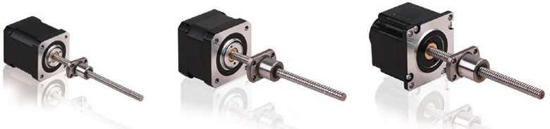
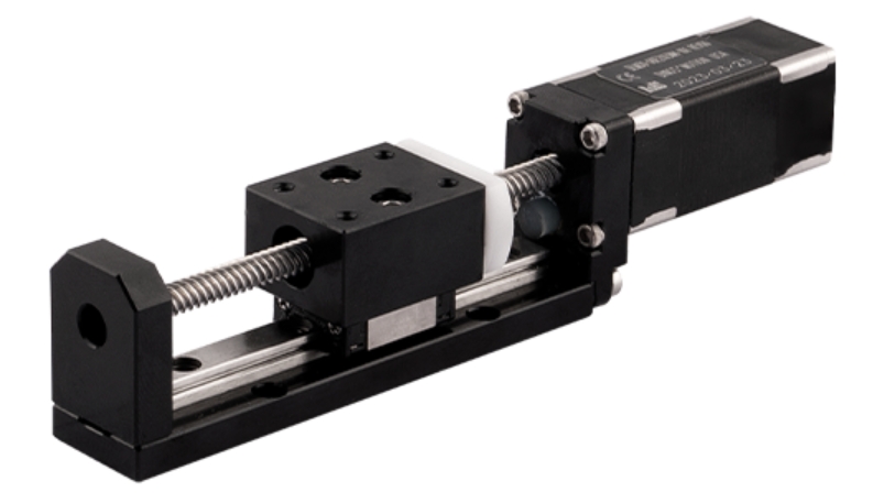
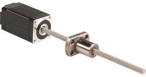
NEMA8 Stepper Ball Screw Linear Actuators
These actuators are external types have 5 different sizes, from 20mm to 57mm. From 0.005mm/
step to 0.1mm/step, variety of resolution for options available. Maximum thrust can reach 1600N.
Encoder option is available for whole Series
| Motor size | NEMA8 | NEMA11 | NEMA14 | NEMA17 | NEMA23 | ||||
| Dia. Lead | Φ4 | Φ5 | Φ6 | Φ6 | Φ8 | Φ6 | Φ8 | Φ10 | Φ12 |
| 1.0 mm | * | * | * | * | * | * | |||
| 2.0 mm | * | * | * | * | * | * | * | * | |
| 2.5 mm | * | * | |||||||
| 4.0 mm | * | * | |||||||
| 5.0 mm | * | * | * | ||||||
| 6.0 mm | * | * | * | ||||||
| 8.0 mm | * | * | |||||||
| 10.0 mm | * | * | * | * | * | * | * | ||
| 12.0 mm | * | * | |||||||
| 15.0 mm | * | ||||||||
| 20.0 mm | * | ||||||||
NEMA8 Stepper Ball Screw Linear Actuators
Motor Characteristics:
| Motor Code | Voltage (V) | Current (A) | Resistance (Ω) | Inductance (mH) | Weight (g) | Lead Wire No | Length (mm) |
| 8E2004 | 3.5 | 0.4 | 8.8 | 2.8 | 51 | 4 | 20 |
| 8E2105 | 2.55 | 0.5 | 5.1 | 1.5 | 74 | 4 | 27.2 |
| 8E2205 | 4.4 | 0.5 | 8.8 | 2.7 | 74 | 4 | 38.1 |
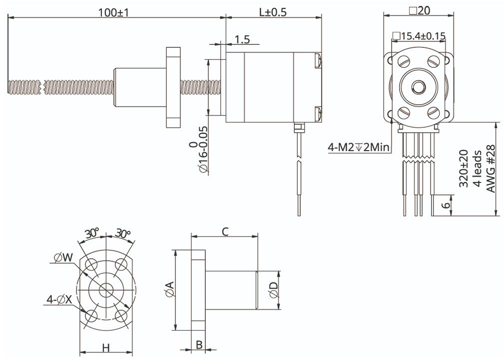
| Ball screw type | SR0401 | SR0402 |
| Ball Diameter | Ф0.8 | Ф0.8 |
| Number of thread | 1 | |
| Thread direction | Right | |
| Shaft root dia. | Ф3.3 | |
| Number of circuit | 3.7×1 | 2.7×1 |
| Shat, nut material | SCM415H | |
| Surface hardness | HRC58~62 | |
| Anti-rust treatment | Anti-rust oil | |
| Nut size | A | B | C | D | H | W | X | Grade | Position accuracy | Total run out | Axial play | Dynamic load(N) | Static load(N) |
| SR0401 | 23 | 4 | 17 | 11 | 15 | 17 | 3.4 | C7 | ±0.05 | 0.12 | 0.02 | 560 | 790 |
| SR0402 | 23 | 4 | 19 | 11 | 15 | 17 | 3.4 | C7 | ±0.05 | 0.12 | 0.02 | 420 | 570 |
NEMA 8 Ball Screw Liner Stepper Motor Performance Curves: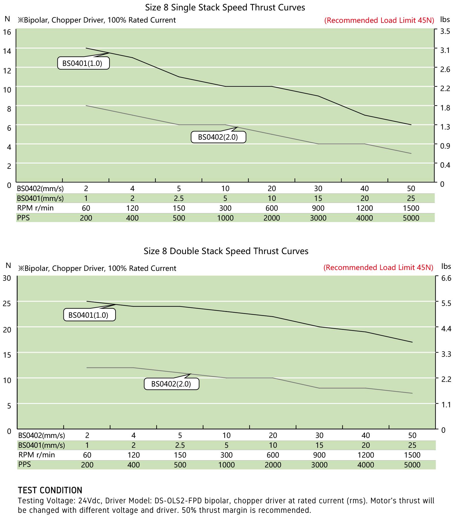
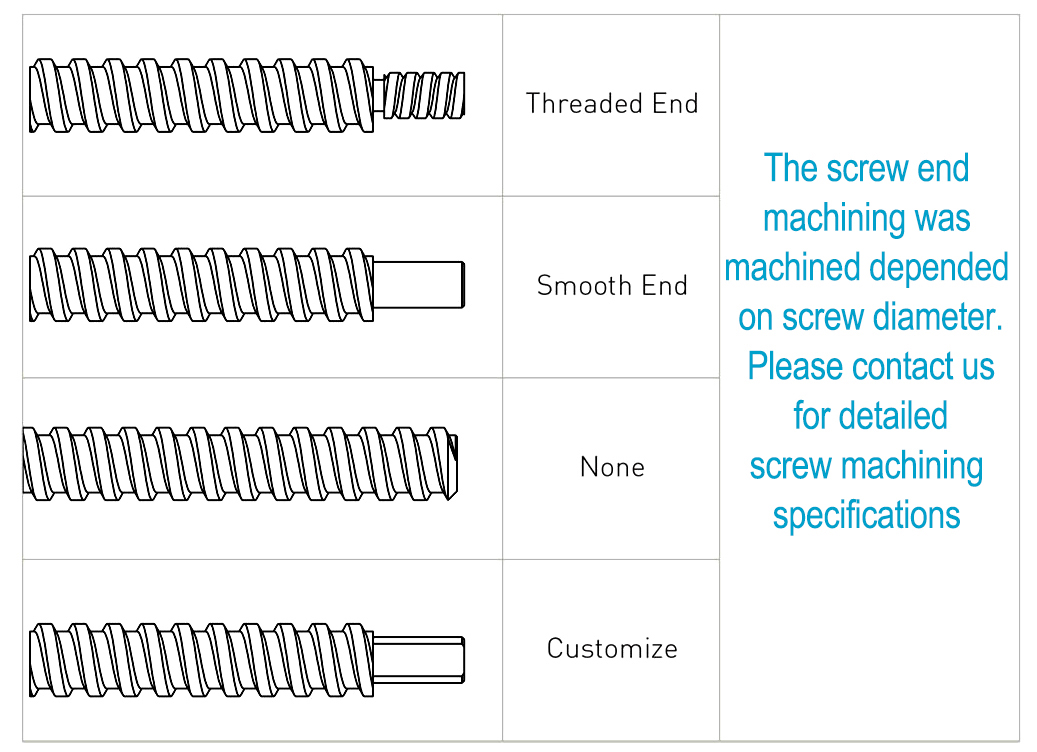
Options for screw end machining:
Catalog for download 
More Information on detail, please feel free to contact me

Pulse & direction stepper motor driver, support to Spontaneous pulses.
Spontaneous pulses Stepper Motor Driver
 | ADH42 | |||
minimum value | Typical value | Maximum value | Unit | |
Supply Voltage (DC) | 12 | 24 | 40 | VDC |
Control Signal | 7 | 10 | 16 | mA |
Step pulse frequency | 0 | - | 200 | KHz |
insulation resistance | 50 |
|
| MΩ |
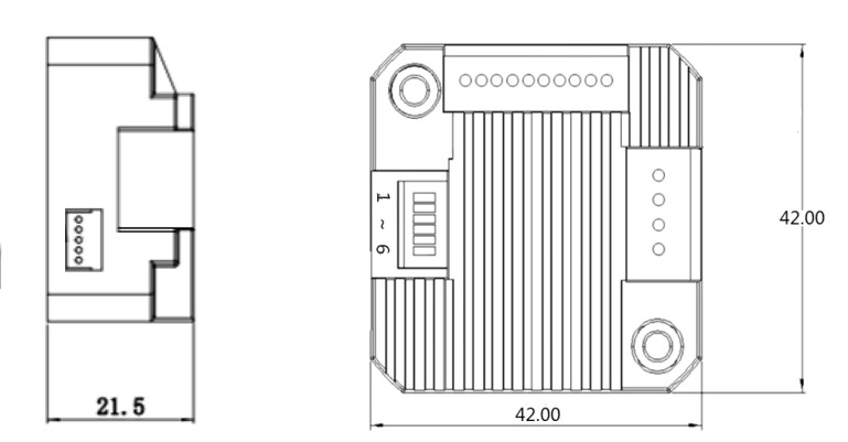
● Miniature size 42mmx42mm x21.5mm
● Pulse & direction stepper driver also support the standard RS232 serial command, and built-in 32bit digital chip.
● Using new control algorithms such for vibration suppression and low heat generation
● DC input voltage 12~40VDC, recommended working voltage 24VDC.
● Continuous output current 1.4A max, max peak current 2.1A.
● Integrated design, mounted with 42/39mm stepper motor.
● Low vibration, low noise, stable operation, low motor heating.
● Any micro-step can be set .
● Protection functions such as overvoltage, undervoltage and overcurrent.
● Built-in automatic matching function of motor parameter.
● ADM42H stepper driver can be assembled for NEMA17 Integrated Stepper Motors
| Pin No. | Name | Description |
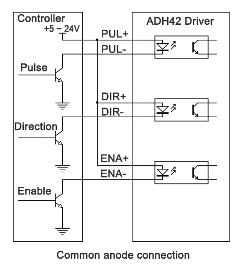
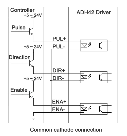
| 1 | PU | Pulse Control Signal Input: 5V ~ 24V, Rising Edge effective, Make sure pulse signal effective, pulse width ≥ 2μs Add the resistance for power supply. |
| 2 | PU- | |
| 3 | DR | Direction Signal: high/low level signal: 5V ~ 24V, direction signal should be at least 5 μs earlier than pulse signal, High/Low level. |
| 4 | DR- | |
| 5 | EN | Enable Signal:enable/disable. If ENA connect 5V & ENA- connect low level(or Internal optocoupler on), stepper controller will turn off the current, motor in free state, no feedback even send pulses. |
| 6 | EN- | |
| 7 | AM | Alarm signal output: When overvoltage, undervoltage, phase loss, or position deviation alarms occur, the alarm signal output is effective; Maximum driving current 50mA |
| 8 | AM- | |
| 9 | GND | Supply Voltage Ground: GND/0V |
| 10 | DC | Supply voltage: 12-40VDC, Recommend DC24V |
Wire support common anode connection and common cathode connection, controlled by PLC or Pulse Generators.
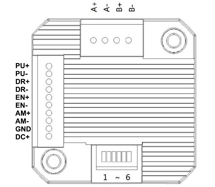
DIP Switch SW1 SW2 SW3 SW4 SW5 SW6 ↑
1. Set working current by SW1:
SW1 | Peak(A) | RMS(A) |
off | 1.4 | 1.0 |
on | 2.1 | 1.5 |
2. Set Working Mode by SW2:
SW2 | Working Mode |
off | Pulse & Direction |
on | Spontaneous pulses |
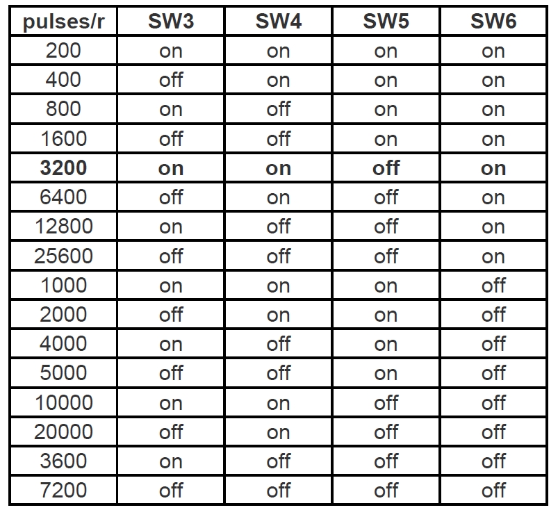
2.1. Pulse & Direction working mode:
Set Micro-step by SW3,SW4,SW5 SW6:
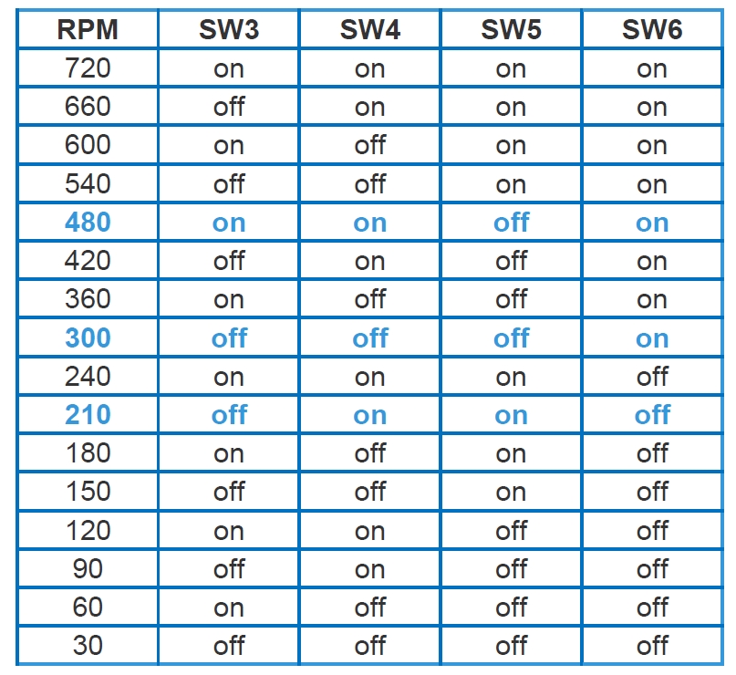
2.1. Spontaneous pulses working mode:
In this working mode, the PU PU- connect to the power supply 5~24VDC and GND,
make sure the stepper motors rotates instantly when power on, please check below wiring diagram:
Set Working Speed by SW3,SW4,SW5 SW6:
More Information on detail, please feel free to contact me

| Step Accuracy: | ±5% | Resistance Accuracy: | ±10% |
|---|---|---|---|
| Inductance Accuracy: | ±20% | Temperature Rise: | 80°C MAX |
| Ambient Temperature Range: | -20°C~ 50°C | Storage Temperature Range: | -30°C~ 60°C |
| Insulation Resistance: | 100M Ω MIN. 500V DC | Dielectric Strength: | 500V AC 1min |
| Radial Play: | 0.02mm MAX. (450g Load) | End Play: | 0.08mm MAX. (450g Load) |
| Max. Radial Force: | 20N | Max. Axial Force: | 2N |
NEMA6 Hollow Shaft Stepper Motor
Electrical Specifications:
Model No. | Step Angle | Motor Length (mm) | Rated voltage (v) | Rated Current (A) | Phase Resistance (Ω) | Phase Indutance (Mh) | Holding Torque(MIN) N.m | Detent Toruue(MAX) N.cm | Motor Torque (g.cm2) |
| 6HS2030 | 1.8 | 32 | 6.6 | 0.3 | 22 | 3.6 | 0.005 | 0.002 | 2.5 |
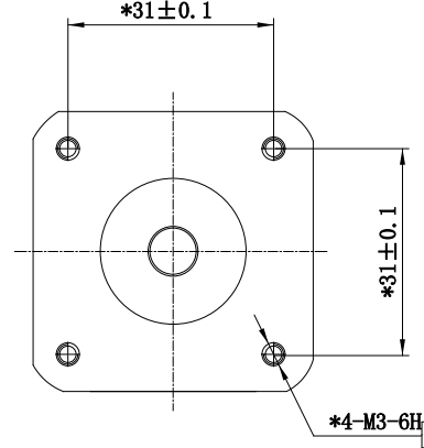
Mechanical Dimensions and Wiring Diagram: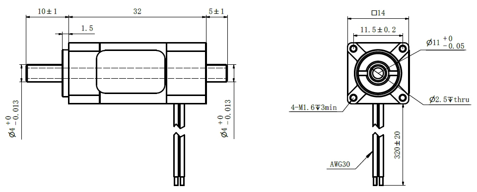
Torque Performance Curve: 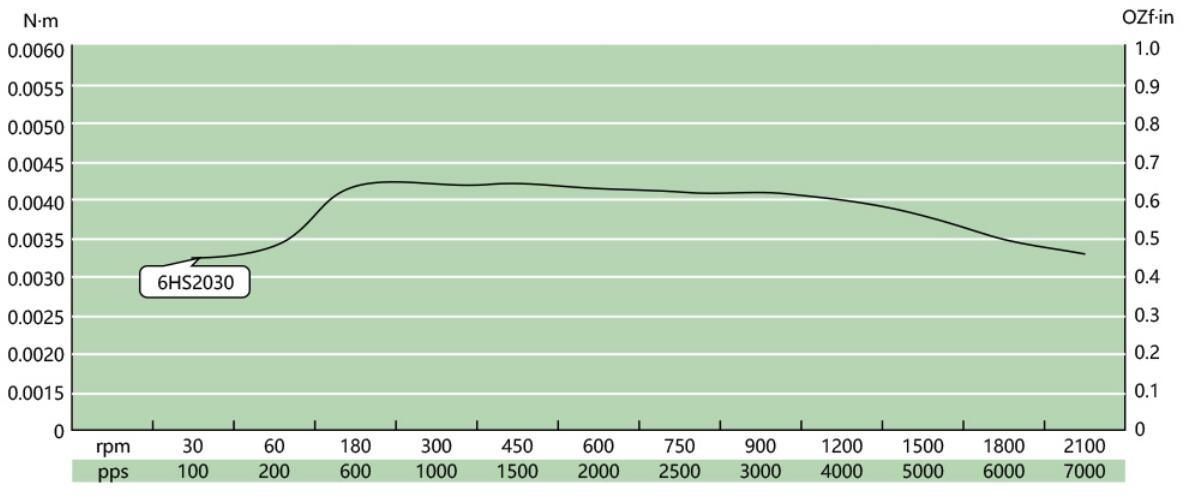
Lead Wire Mode Options:
More Information on detail, please feel free to contact me

| Step Accuracy: | ±5% | Resistance Accuracy: | ±10% |
|---|---|---|---|
| Inductance Accuracy: | ±20% | Temperature Rise: | 80°C MAX |
| Ambient Temperature Range: | -20°C~ 50°C | Storage Temperature Range: | -30°C~ 60°C |
| Insulation Resistance: | 100M Ω MIN. 500V DC | Dielectric Strength: | 500V AC 1min |
| Radial Play: | 0.02mm MAX. (450g Load) | End Play: | 0.08mm MAX. (450g Load) |
| Max. Radial Force: | 20N | Max. Axial Force: | 2N |
NEMA8 Hollow Shaft Stepper Motor
Electrical Specifications:
Model No. | Step Angle | Motor Length (mm) | Rated voltage (v) | Rated Current (A) | Phase Resistance (Ω) | Phase Indutance (Mh) | Holding Torque(MIN) N.cm | Detent Toruue(MAX) N.cm | Motor Torque (g.cm2) | Lead Wire | Motor Weight (g) |
| 8HS2028 | 1.8 | 27.2 | 2.55 | 0.5 | 5.1 | 1.5 | 1.4 | 0.2 | 2.5 | 4 | 50 |
| 8HS2038 | 1.8 | 28.1 | 4.4 | 0.5 | 8.8 | 2.7 | 2.0 | 0.2 | 4.5 | 4 | 70 |
Mechanical Dimensions and Wiring Diagram: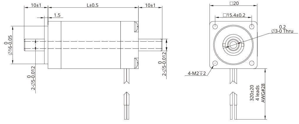
Torque Performance Curve: 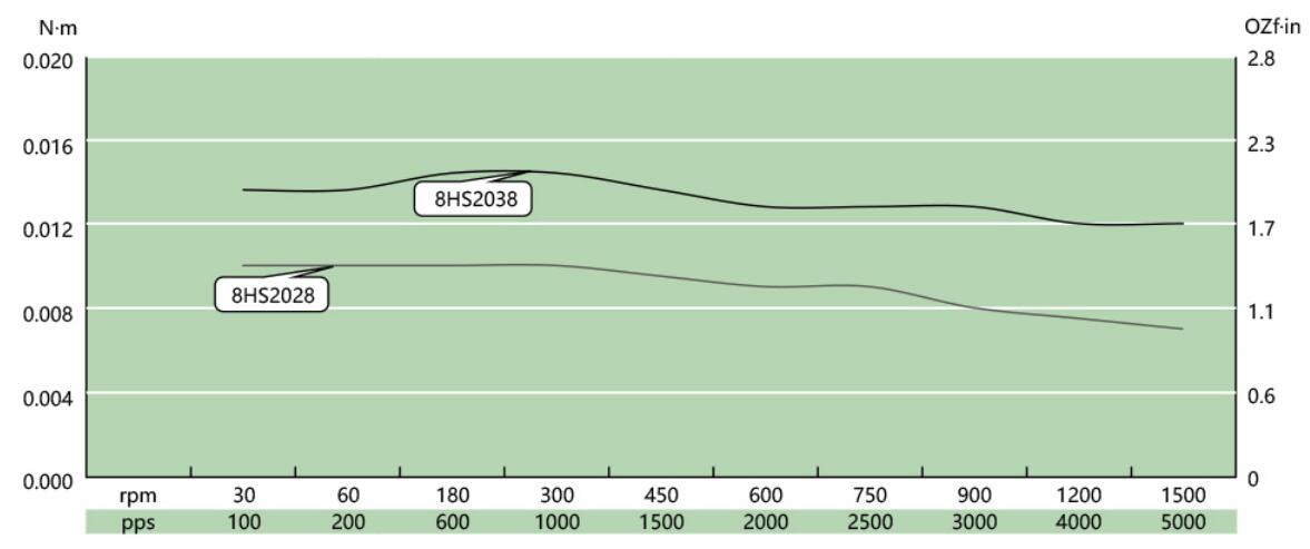
Lead Wire Mode Options:
More Information on detail, please feel free to contact me

| Step Accuracy: | ±5% | Resistance Accuracy: | ±10% |
|---|---|---|---|
| Inductance Accuracy: | ±20% | Temperature Rise: | 80°C MAX |
| Ambient Temperature Range: | -20°C~ 50°C | Storage Temperature Range: | -30°C~ 60°C |
| Insulation Resistance: | 100M Ω MIN. 500V DC | Dielectric Strength: | 500V AC 1min |
| Radial Play: | 0.02mm MAX. (450g Load) | End Play: | 0.08mm MAX. (450g Load) |
| Max. Radial Force: | 20N | Max. Axial Force: | 2N |
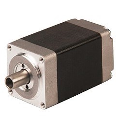
NEMA14 Hollow Shaft Stepper Motor
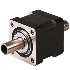
Electrical Specifications:
Model No. | Step Angle | Motor Length (mm) | Rated voltage (v) | Rated Current (A) | Phase Resistance (Ω) | Phase Indutance (Mh) | Holding Torque(MIN) N.cm | Detent Toruue(MAX) N.cm | Lead Wire |
| 14HS2033 | 1.8 | 33.6 | 3.5 | 1.0 | 3.5 | 3.6 | 19 | 0.8 | 4 |
| 14HS2045 | 1.8 | 45.6 | 6.0 | 1.0 | 6.0 | 7.2 | 36 | 1.3 | 4 |
Mechanical Dimensions and Wiring Diagram: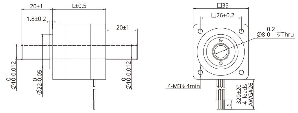
Torque Performance Curve: 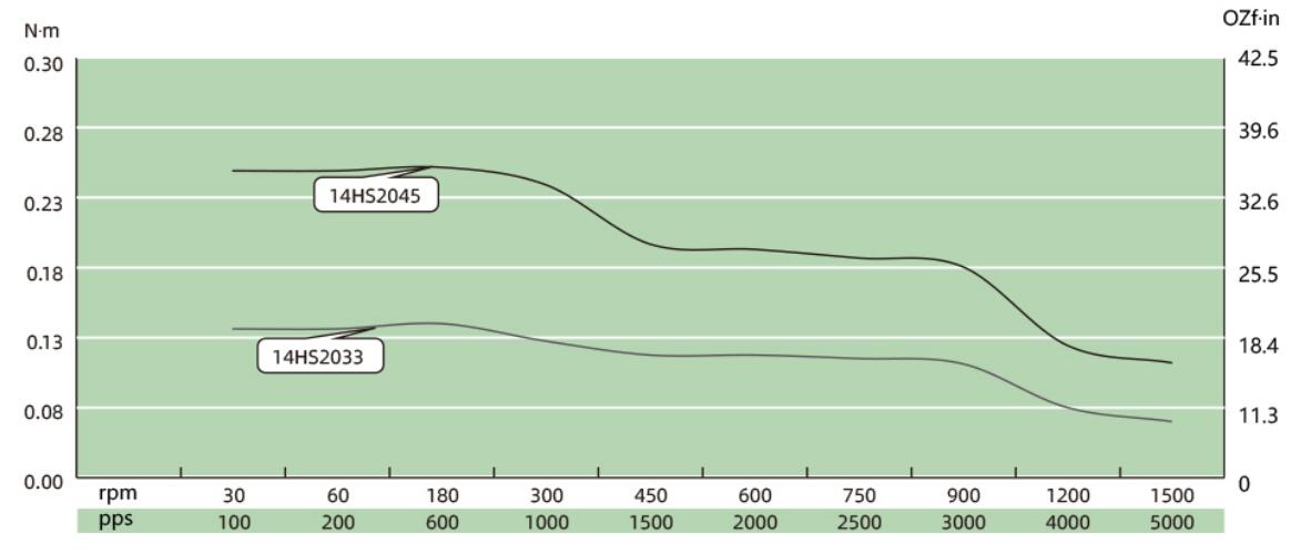
Lead Wire Mode Options:
More Information on detail, please feel free to contact me

| Step Accuracy: | ±5% | Resistance Accuracy: | ±10% |
|---|---|---|---|
| Inductance Accuracy: | ±20% | Temperature Rise: | 80°C MAX |
| Ambient Temperature Range: | -20°C~ 50°C | Storage Temperature Range: | -30°C~ 60°C |
| Insulation Resistance: | 100M Ω MIN. 500V DC | Dielectric Strength: | 500V AC 1min |
| Radial Play: | 0.02mm MAX. (450g Load) | End Play: | 0.08mm MAX. (450g Load) |
| Max. Radial Force: | 20N | Max. Axial Force: | 2N |
NEMA11 Hollow Shaft Stepper Motor
Electrical Specifications:
Model No. | Step Angle | Motor Length (mm) | Rated voltage (v) | Rated Current (A) | Phase Resistance (Ω) | Phase Indutance (Mh) | Holding Torque(MIN) N.cm | Detent Toruue(MAX) N.cm | Lead Wire |
| 11HS2033 | 1.8 | 33.5 | 2.1 | 1.0 | 2.1 | 1.5 | 5.3 | 0.4 | 4 |
| 11HS2045 | 1.8 | 45.0 | 4.1 | 1.0 | 4.1 | 4.0 | 11.7 | 0.4 | 4 |
Mechanical Dimensions and Wiring Diagram: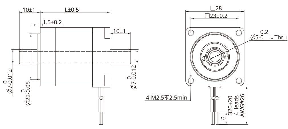
Torque Performance Curve: 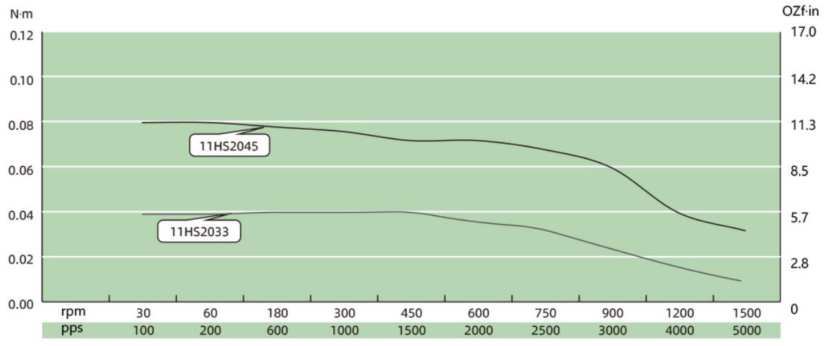
Lead Wire Mode Options:
More Information on detail, please feel free to contact me

| Step Accuracy: | ±5% | Resistance Accuracy: | ±10% |
|---|---|---|---|
| Inductance Accuracy: | ±20% | Temperature Rise: | 80°C MAX |
| Ambient Temperature Range: | -20°C~ 50°C | Storage Temperature Range: | -30°C~ 60°C |
| Insulation Resistance: | 100M Ω MIN. 500V DC | Dielectric Strength: | 500V AC 1min |
| Radial Play: | 0.02mm MAX. (450g Load) | End Play: | 0.08mm MAX. (450g Load) |
| Max. Radial Force: | 20N | Max. Axial Force: | 2N |
NEMA23 Hollow Shaft Stepper Motor
Electrical Specifications:
Model No. | Step Angle | Motor Length (mm) | Rated Current (A) | Phase Resistance (Ω) | Phase Indutance (Mh) | Holding Torque(MIN) N.m | Lead Wire | Weight (Kg) |
| 23HS45 | 1.8 | 45 | 2.0 | 1.75 | 4.1 | 0.8 | 4 | 0.6 |
| 23HS65 | 1.8 | 65 | 4.0 | 0.7 | 2.0 | 2.1 | 4 | 0.8 |
| 23HS76 | 1.8 | 76 | 4.0 | 0.65 | 2.5 | 2.0 | 4 | 1.1 |
Mechanical Dimensions and Wiring Diagram: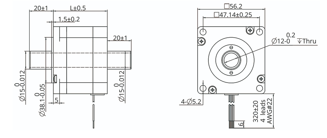
Torque Performance Curve: 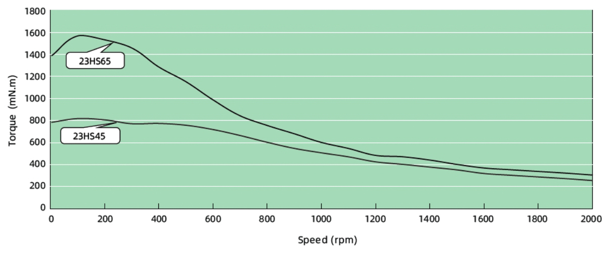
Lead Wire Mode Options:
More Information on detail, please feel free to contact me
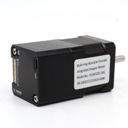
The IS14 series integrated motor is the perfect combination of drive and stepper motor,
which perfectly integrates stepper motor and drive technology, also built in a battery free
1023 turn mechanical absolute value encoder, it can save installation space,
Simultaneously saving design and production costs, supporting RS485 instruction control.
| Item | Specifications |
| Stepper Motor Size | NEMA14 |
| Encoder type | 1023 ring absolute encoder |
| Working voltage | 8-36V |
| Driver Current | 0.2-2.0A |
| Velocity range | Up to 3000RPM |
| Control Method | RS485 √ Pulse& Direction, Twin-Pulse, I/O, Built-in Program |
| Torque value | 0.1 - 0.4Nm |
| Nonvolatile storage | Configuration parameters are stored in FLASH inside the MCU |
| DI and DO | 2 DI, 1 DO |
| Protection | Overvoltage, undervoltage, overcurrent, open winding, position deviation |
| Digital Input (2) | Receive 3.3-24VDC | ||
| Digital Output(1) | Maximum withstand voltage of 30V, | ||
| Maximum input or output current 30mA | |||
Motor Parameters
| Model No. | length mm L | Shaft length mm | Shaft dia. mm | Phase current A | Resistance Ω | inductance mH | Hold torque N.m | Inertia g.cm² | Weight g |
| IS14010 | 52 | 24 | 5 | 1.0 | 2.55 | 2.0 | 0.1 | 12 | 240 |
| IS14020 | 62 | 24 | 5 | 1.5 | 1.65 | 2.1 | 0.2 | 20 | 300 |
| IS14040 | 80 | 24 | 5 | 1.8 | 1.85 | 2.8 | 0.4 | 35 | 350 |
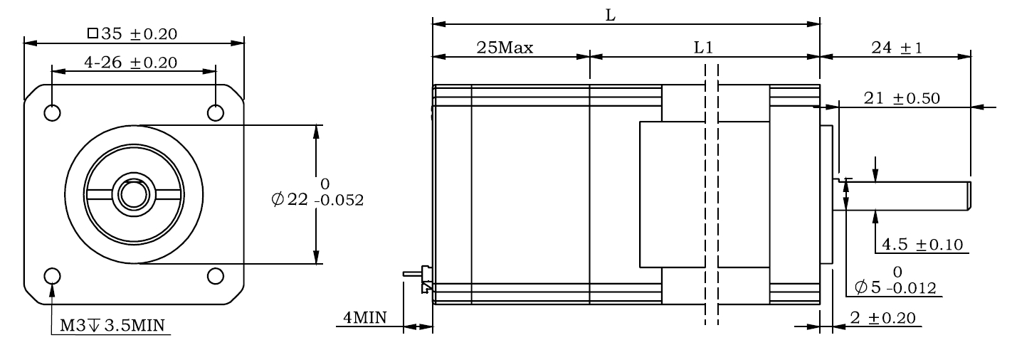
Wiring Diagram: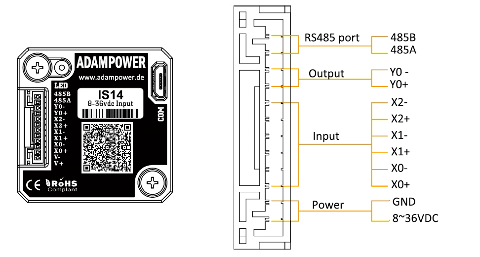
Terminal Definition
| Terminal | Name | Description | |
| 1 | V | 8-36VDC | |
| 2 | V- | GND | |
| 3 | X0 (PU ) | Optoelectronic isolation, differential, High level can directly receive 3.3-24VDC, with a minimum pulse width of 2us, The maximum pulse frequency is 400KHz, which can be used as a universal input port for Pulse/Direction | |
| 4 | X0-(PU-) | ||
| 5 | X1 (DR ) | ||
| 6 | X1-(DR-) | ||
| 7 | X2(EN ) | Optoelectronic isolation, differential, High level can directly receive 3.3-24VDC, with a minimum pulse width of 100us, The maximum pulse frequency is 10KHz, which can be used as a universal input port for Enable | |
| 8 | X2-(EN-) | ||
| 9 | Y0 (AL ) | The default alarm output port can detect the driver alarm status and provide feedback to the main station. Other functions can be set through communication | |
| 10 | Y0-(AL-) | ||
| 11 | 485A | RS485 Communication port, default baud rate is 115200 | |
| 12 | 485B | ||
Block Diagram:
2 Input signals can directly receive 3.3-24V DC levels at high levels, Max. frequency of 400KHZ.
X0: pulse input, IO start/stop, limit, direction, universal input.
X1 pulse input, IO start/stop, limit, direction, universal input.
1 Output signal, maximum withstand voltage 30V, maximum input or output current 30mA
Y0 : alarm output, universal output, and factory default alarm output.
LED indicator and status:
CRC Check routine by C# :
Uint16 Funct_CRC16(unsigned char * puchMsg, Uint16 DataLen)
{
Uint16 i,j,tmp;
Uint16 crcdata=0xFFFF;
for(i=0;i<DataLen;i )
{
crcdata=(*puchMsg)^crcdata;
puchMsg ;
for(j=0;j<8;j )
{
tmp=crcdata&0x0001;
crcdata=crcdata>>1;
if(tmp){
crcdata=crcdata^0xA001;
}
}
}
returncrcdata;
}
Software Modbus Poll
Software Step-Config
1. Extract the zip file, open CommFile and Click Step-Config.exe
2. Right Click Modbus_485, and Click Property:
3. Click Property ComNN, Choose COM port, Baud rate and click Save and OK.
4. Start to use software control the RS485 Integrated stepper motor by below buttons:
RS485 Stepper Motor Controller Manual
Block Diagram:
2 Input signals can directly receive 3.3-24V DC levels at high levels, Max. frequency of 400KHZ.
X0: pulse input, IO start/stop, limit, direction, universal input.
X1 pulse input, IO start/stop, limit, direction, universal input.
...
1 Output signal, maximum withstand voltage 30V, maximum input or output current 30mA
Y0 : alarm output, universal output, and factory default alarm output.
LED indicator and status:

The IG17 series integrated motor is the perfect combination of drive and stepper motor,
which perfectly integrates stepper motor and drive technology, also built in 1000 line encoder,
it can save installation space, Simultaneously saving design and production costs,
supporting RS485 and TTL communication.
| Item | Specifications |
| Stepper Motor Size | NEMA17 |
| Encoder type | 1000 line encoder |
| Working voltage | 8-50VDC, Recommend DC36V |
| Driver Current | 0.2-3.2A |
| Velocity range | Up to 3000RPM |
| Control Method | RS485, Pulse& Direction, Twin-Pulse, I/O, Built-in Program |
| Torque value | 0.2 - 6Nm |
| Nonvolatile storage | Configuration parameters are stored in FLASH inside the MCU |
| DI and DO | 2 DI, 1 DO |
| Protection | Overvoltage, undervoltage, overcurrent, open winding, position deviation |
| Digital Input (2/3) | Receive 3.3-24VDC | ||
| Digital Output(1) | Maximum withstand voltage of 30V, | ||
| Maximum input or output current 30mA | |||
Motor Parameters
| Model No. | length mm L | Shaft length mm | Shaft dia. mm | Phase current A | Resistance Ω | inductance mH | Hold torque N.m | Inertia g.cm² | Weight g |
| IG1704 | 40 | 21 | 8 | 2.0 | 2 | 4.2 | 0.4 | 57 | 380 |
| IG1705 | 48 | 21 | 8 | 2.0 | 1.3 | 2.9 | 0.5 | 82 | 460 |
| IG1706 | 60 | 21 | 8 | 2.5 | 1.3 | 3.2 | 0.6 | 116 | 700 |
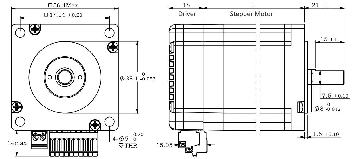
Wiring Diagram:
~~~~~~~~~~~~~~~~~~~~~~~~~~~~~~~~~~~~~~~~~~~~~~~~~~~~~~~~~~~~~~~~~~~~~~~~~~~~~~~~~~~~~~~~~~~
1. Pulse Type Integrated Stepper Motor, Terminal definition.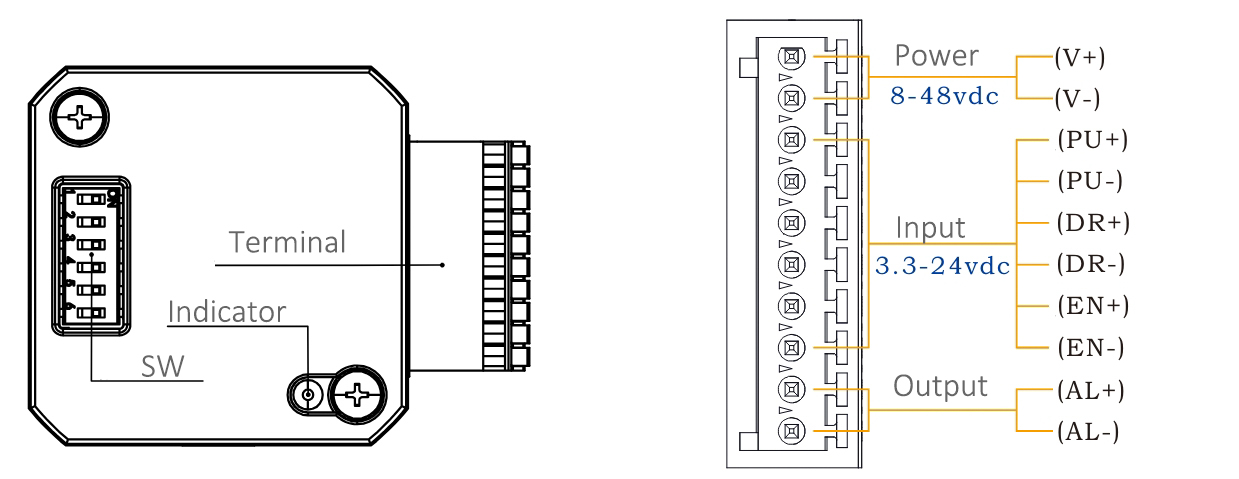
Terminal Definition
| Terminal | Name | Description | |
| 1 | V | 8-48VDC | |
| 2 | V- | GND | |
| 3 | X0 (PU ) | Optoelectronic isolation, differential, High level can directly receive 3.3-24VDC, with a minimum pulse width of 2us, The maximum pulse frequency is 400KHz, which can be used as a universal input port for Pulse/Direction | |
| 4 | X0-(PU-) | ||
| 5 | X1 (DR ) | ||
| 6 | X1-(DR-) | ||
| 7 | X2(EN ) | Optoelectronic isolation, differential, High level can directly receive 3.3-24VDC, with a minimum pulse width of 100us, The maximum pulse frequency is 10KHz, which can be used as a universal input port for Enable | |
| 8 | X2(EN-) | ||
| 9 | Y0 (AL ) | The default alarm output port can detect the driver alarm status and provide feedback to the main station. Other functions can be set through communication | |
| 10 | Y0-(AL-) | ||
Set Micro-step by SW1, SW2, SW3 and SW4: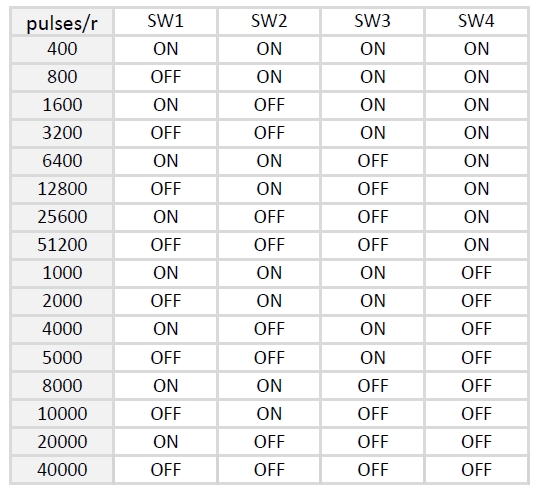
SW5=OFF: Pulse & Direction; SW=ON: Twin Pulse mode.
SW6=OFF: CW direction; SW6=ON: CCW direction.
~~~~~~~~~~~~~~~~~~~~~~~~~~~~~~~~~~~~~~~~~~~~~~~~~~~~~~~~~~~~~~~~~~~~~~~~~~~~~~~~~~~~~~~~~
2. RS485 Type Integrated Stepper Motor, Terminal definition.
Terminal Definition
| Terminal | Name | Description | |
| 1 | V | 8-48VDC | |
| 2 | V- | GND | |
| 3 | X0 (PU ) | Optoelectronic isolation, differential, High level can directly receive 3.3-24VDC, with a minimum pulse width of 2us, The maximum pulse frequency is 400KHz, which can be used as a universal input port or a high-speed pulse input port | |
| 4 | X0-(PU-) | ||
| 5 | X1 (DR ) | ||
| 6 | X1-(DR-) | ||
| 7 | 485A(EN ) | RS485 Communication port, default baud rate is 115200, | |
| 8 | 485B(EN-) | ||
| 9 | Y0 (AL ) | The default alarm output port can detect the driver alarm status and provide feedback to the main station. Other functions can be set through communication | |
| 10 | Y0-(AL-) | ||
Set Device ID for RS485 integrated Stepper Motor by SW1 ~ SW5:
SW6 is used to set the terminal resistance; OFF=0 ohms; ON=120 ohms
CRC Check routine by C# :
Uint16 Funct_CRC16(unsigned char * puchMsg, Uint16 DataLen)
{
Uint16 i,j,tmp;
Uint16 crcdata=0xFFFF;
for(i=0;i<DataLen;i )
{
crcdata=(*puchMsg)^crcdata;
puchMsg ;
for(j=0;j<8;j )
{
tmp=crcdata&0x0001;
crcdata=crcdata>>1;
if(tmp){
crcdata=crcdata^0xA001;
}
}
}
returncrcdata;
}
Software Modbus Poll
Software Step-Config
1. Extract the zip file, open CommFile and Click Step-Config.exe
2. Right Click Modbus_485, and Click Property:
3. Click Property ComNN, Choose COM port, Baud rate and click Save and OK.
4. Start to use software control the RS485 Integrated stepper motor by below buttons:
RS485 Stepper Motor Controller Manual
Block Diagram:
2 Input signals can directly receive 3.3-24V DC levels at high levels, Max. frequency of 400KHZ.
X0: pulse input, IO start/stop, limit, direction, universal input.
X1 pulse input, IO start/stop, limit, direction, universal input.
...
1 Output signal, maximum withstand voltage 30V, maximum input or output current 30mA
Y0 : alarm output, universal output, and factory default alarm output.
LED indicator and status:

The IG23 series integrated motor is the perfect combination of drive and stepper motor,
which perfectly integrates stepper motor and drive technology, also built in 1000 line encoder,
it can save installation space, Simultaneously saving design and production costs,
supporting RS485 and TTL communication.
| Item | Specifications |
| Stepper Motor Size | NEMA23 |
| Encoder type | 1000 line encoder |
| Working voltage | 8-60VDC, Recommend DC36V |
| Driver Current | 0.5-5A |
| Velocity range | Up to 3000RPM |
| Control Method | RS485, Pulse& Direction, Twin-Pulse, I/O, Built-in Program |
| Torque value | 0.8 - 2.2Nm |
| Nonvolatile storage | Configuration parameters are stored in FLASH inside the MCU |
| DI and DO | 2 DI, 1 DO |
| Protection | Overvoltage, undervoltage, overcurrent, open winding, position deviation |
| Digital Input (2/3) | Receive 3.3-24VDC | ||
| Digital Output(1) | Maximum withstand voltage of 30V, | ||
| Maximum input or output current 30mA | |||
Motor Parameters
| Model No. | length mm L | Shaft length mm | Shaft dia. mm | Phase current A | Resistance Ω | inductance mH | Hold torque N.m | Inertia g.cm² | Weight g |
| IG2312 | 68 | 21 | 8 | 4 | 0.5 | 1.8 | 1.2 | 280 | 800 |
| IG2320 | 85 | 21 | 8 | 5 | 0.4 | 2.0 | 2.0 | 480 | 1100 |
Wiring Diagram:
~~~~~~~~~~~~~~~~~~~~~~~~~~~~~~~~~~~~~~~~~~~~~~~~~~~~~~~~~~~~~~~~~~~~~~~~~~~~~~~~~~~~~~~~~~~
1. Pulse Type Integrated Stepper Motor, Terminal definition.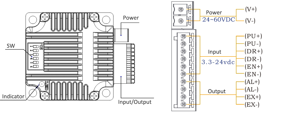
Terminal Definition
| Terminal | Name | Description | |
| 1 | V | 24~60VDC | |
| 2 | V- | GND | |
| 3 | X0 (PU ) | Optoelectronic isolation, differential, High level can directly receive 3.3-24VDC, with a minimum pulse width of 2us, The maximum pulse frequency is 400KHz, which can be used as a universal input port for Pulse/Direction | |
| 4 | X0-(PU-) | ||
| 5 | X1 (DR ) | ||
| 6 | X1-(DR-) | ||
| 7 | X2(EN ) | Optoelectronic isolation, differential, High level can directly receive 3.3-24VDC, with a minimum pulse width of 100us, The maximum pulse frequency is 10KHz, which can be used as a universal input port for Enable | |
| 8 | X2(EN-) | ||
| 9 | Y0 (AL ) | The default alarm output port can detect the driver alarm status and provide feedback to the main station. Other functions can be set through communication | |
| 10 | Y0-(AL-) | ||
| 11 | Y1(EX ) | The default In-place output , Other functions can be set through communication | |
| 12 | Y1(EX-) | ||
Set Micro-step by SW1, SW2, SW3 and SW4:
SW5=OFF: Pulse & Direction; SW=ON: Twin Pulse mode.
SW6=OFF: CW direction; SW6=ON: CCW direction.
~~~~~~~~~~~~~~~~~~~~~~~~~~~~~~~~~~~~~~~~~~~~~~~~~~~~~~~~~~~~~~~~~~~~~~~~~~~~~~~~~~~~~~~~~
2. RS485 Type Integrated Stepper Motor, Terminal definition.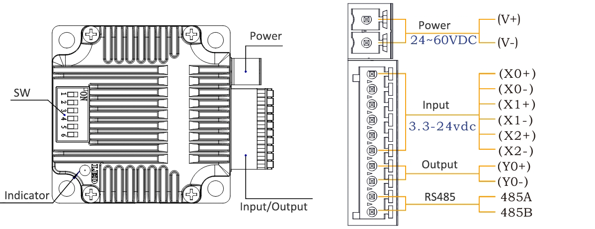
Terminal Definition
| Terminal | Name | Description | |
| 1 | V | 24~60VDC | |
| 2 | V- | GND | |
| 3 | X0 (PU ) | Optoelectronic isolation, differential, High level can directly receive 3.3-24VDC, with a minimum pulse width of 2us, The maximum pulse frequency is 400KHz, which can be used as a universal input port for Pulse/Direction/Enable | |
| 4 | X0-(PU-) | ||
| 5 | X1 (DR ) | ||
| 6 | X1-(DR-) | ||
| 7 | X2 (EN ) | ||
| 8 | X2-(EN-) | ||
| 9 | Y0 (AL ) | The default alarm output port can detect the driver alarm status and provide feedback to the main station. Other functions can be set through communication | |
| 10 | Y0-(AL-) | ||
| 11 | 485A | RS485 Communication port, default baud rate is 115200 | |
| 12 | 485B | ||
Set Device ID for RS485 integrated Stepper Motor by SW1 ~ SW5:
SW6 is used to set the terminal resistance; OFF=0 ohms; ON=120 ohms
CRC Check routine by C# :
Uint16 Funct_CRC16(unsigned char * puchMsg, Uint16 DataLen)
{
Uint16 i,j,tmp;
Uint16 crcdata=0xFFFF;
for(i=0;i<DataLen;i )
{
crcdata=(*puchMsg)^crcdata;
puchMsg ;
for(j=0;j<8;j )
{
tmp=crcdata&0x0001;
crcdata=crcdata>>1;
if(tmp){
crcdata=crcdata^0xA001;
}
}
}
returncrcdata;
}
Software Modbus Poll
Software Step-Config
1. Extract the zip file, open CommFile and Click Step-Config.exe
2. Right Click Modbus_485, and Click Property:
3. Click Property ComNN, Choose COM port, Baud rate and click Save and OK.
4. Start to use software control the RS485 Integrated stepper motor by below buttons:
RS485 Stepper Motor Controller Manual
Block Diagram:
2 Input signals can directly receive 3.3-24V DC levels at high levels, Max. frequency of 400KHZ.
X0: pulse input, IO start/stop, limit, direction, universal input.
X1 pulse input, IO start/stop, limit, direction, universal input.
...
1 Output signal, maximum withstand voltage 30V, maximum input or output current 30mA
Y0 : alarm output, universal output, and factory default alarm output.
LED indicator and status: