
Adampower
![]()
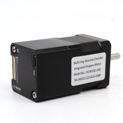
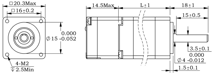
The IS14 series integrated motor is the perfect combination of drive and stepper motor,
which perfectly integrates stepper motor and drive technology, also built in a battery free
1023 turn mechanical absolute value encoder, it can save installation space,
Simultaneously saving design and production costs, supporting RS485 instruction control.
| Item | Specifications |
| Stepper Motor Size | NEMA14 |
| Encoder type | 1023 ring absolute encoder |
| Working voltage | 8-36V |
| Driver Current | 0.2-2.0A |
| Velocity range | Up to 3000RPM |
| Control Method | RS485 √ Pulse& Direction, Twin-Pulse, I/O, Built-in Program |
| Torque value | 0.1 - 0.4Nm |
| Nonvolatile storage | Configuration parameters are stored in FLASH inside the MCU |
| DI and DO | 2 DI, 1 DO |
| Protection | Overvoltage, undervoltage, overcurrent, open winding, position deviation |
| Digital Input (2) | Receive 3.3-24VDC | ||
| Digital Output(1) | Maximum withstand voltage of 30V, | ||
| Maximum input or output current 30mA | |||
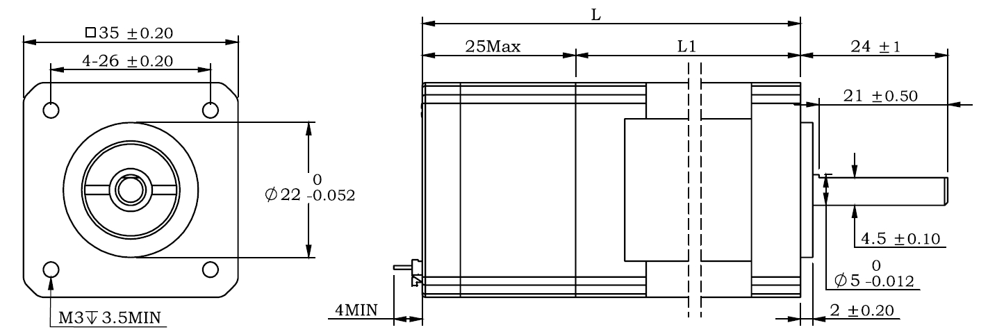
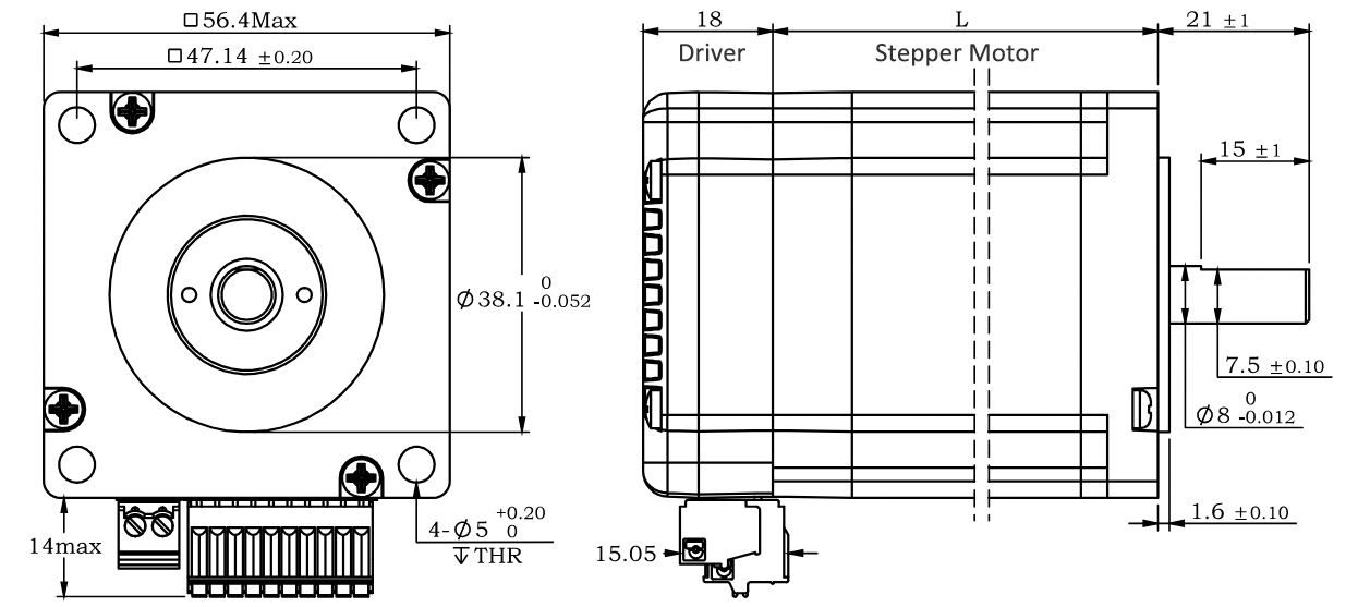
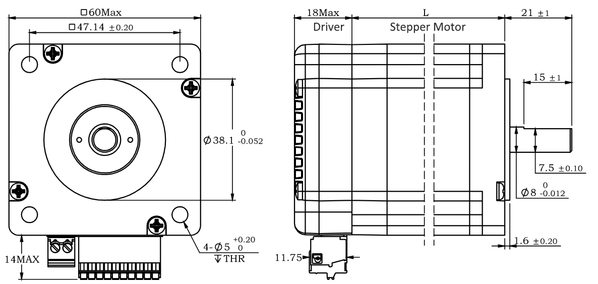
Motor Parameters
| Model No. | length mm L | Shaft length mm | Shaft dia. mm | Phase current A | Resistance Ω | inductance mH | Hold torque N.m | Inertia g.cm² | Weight g |
| IS14010 | 52 | 24 | 5 | 1.0 | 2.55 | 2.0 | 0.1 | 12 | 240 |
| IS14020 | 62 | 24 | 5 | 1.5 | 1.65 | 2.1 | 0.2 | 20 | 300 |
| IS14040 | 80 | 24 | 5 | 1.8 | 1.85 | 2.8 | 0.4 | 35 | 350 |
Wiring Diagram: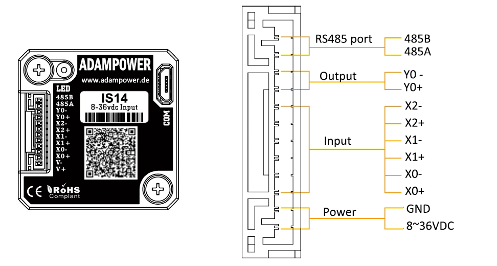
Terminal Definition
| Terminal | Name | Description | |
| 1 | V | 8-36VDC | |
| 2 | V- | GND | |
| 3 | X0 (PU ) | Optoelectronic isolation, differential, High level can directly receive 3.3-24VDC, with a minimum pulse width of 2us, The maximum pulse frequency is 400KHz, which can be used as a universal input port for Pulse/Direction | |
| 4 | X0-(PU-) | ||
| 5 | X1 (DR ) | ||
| 6 | X1-(DR-) | ||
| 7 | X2(EN ) | Optoelectronic isolation, differential, High level can directly receive 3.3-24VDC, with a minimum pulse width of 100us, The maximum pulse frequency is 10KHz, which can be used as a universal input port for Enable | |
| 8 | X2-(EN-) | ||
| 9 | Y0 (AL ) | The default alarm output port can detect the driver alarm status and provide feedback to the main station. Other functions can be set through communication | |
| 10 | Y0-(AL-) | ||
| 11 | 485A | RS485 Communication port, default baud rate is 115200 | |
| 12 | 485B | ||
Block Diagram:
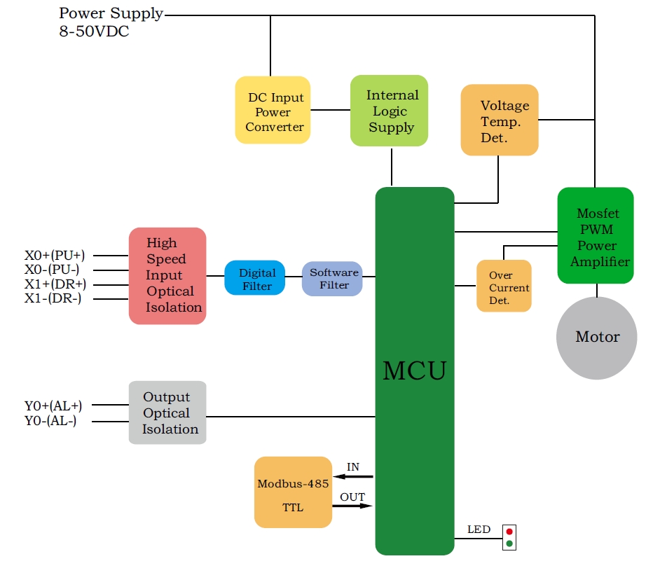
2 Input signals can directly receive 3.3-24V DC levels at high levels, Max. frequency of 400KHZ.
X0: pulse input, IO start/stop, limit, direction, universal input.
X1 pulse input, IO start/stop, limit, direction, universal input.
1 Output signal, maximum withstand voltage 30V, maximum input or output current 30mA
Y0 : alarm output, universal output, and factory default alarm output.
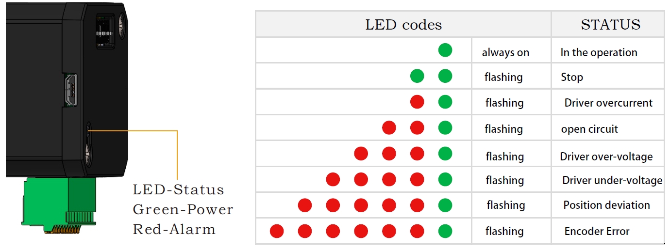
LED indicator and status:
CRC Check routine by C# :
Uint16 Funct_CRC16(unsigned char * puchMsg, Uint16 DataLen)
{
Uint16 i,j,tmp;
Uint16 crcdata=0xFFFF;
for(i=0;i<DataLen;i )
{
crcdata=(*puchMsg)^crcdata;
puchMsg ;
for(j=0;j<8;j )
{
tmp=crcdata&0x0001;
crcdata=crcdata>>1;
if(tmp){
crcdata=crcdata^0xA001;
}
}
}
returncrcdata;
}
Software Modbus Poll 
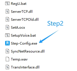
Software Step-Config
1. Extract the zip file, open CommFile and Click Step-Config.exe
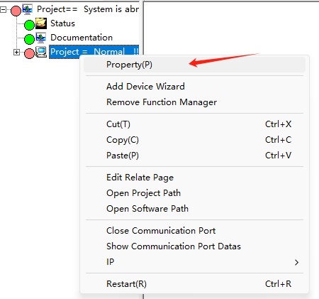
2. Right Click Modbus_485, and Click Property: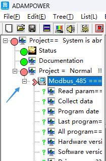
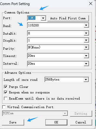
3. Click Property ComNN, Choose COM port, Baud rate and click Save and OK.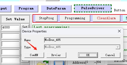
4. Start to use software control the RS485 Integrated stepper motor by below buttons: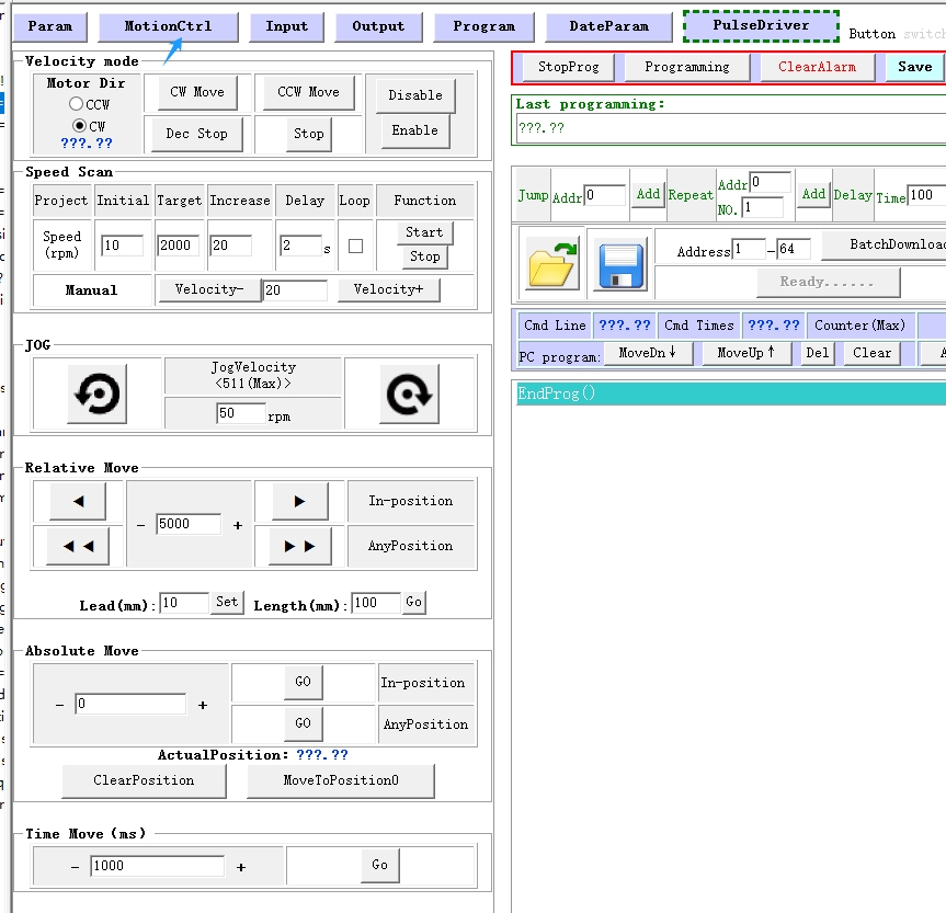
RS485 Stepper Motor Controller Manual 
Block Diagram:
2 Input signals can directly receive 3.3-24V DC levels at high levels, Max. frequency of 400KHZ.
X0: pulse input, IO start/stop, limit, direction, universal input.
X1 pulse input, IO start/stop, limit, direction, universal input.
...
1 Output signal, maximum withstand voltage 30V, maximum input or output current 30mA
Y0 : alarm output, universal output, and factory default alarm output.
LED indicator and status:

The IG17 series integrated motor is the perfect combination of drive and stepper motor,
which perfectly integrates stepper motor and drive technology, also built in 1000 line encoder,
it can save installation space, Simultaneously saving design and production costs,
supporting RS485 and TTL communication.
| Item | Specifications |
| Stepper Motor Size | NEMA17 |
| Encoder type | 1000 line encoder |
| Working voltage | 8-50VDC, Recommend DC36V |
| Driver Current | 0.2-3.2A |
| Velocity range | Up to 3000RPM |
| Control Method | RS485, Pulse& Direction, Twin-Pulse, I/O, Built-in Program |
| Torque value | 0.2 - 6Nm |
| Nonvolatile storage | Configuration parameters are stored in FLASH inside the MCU |
| DI and DO | 2 DI, 1 DO |
| Protection | Overvoltage, undervoltage, overcurrent, open winding, position deviation |
| Digital Input (2/3) | Receive 3.3-24VDC | ||
| Digital Output(1) | Maximum withstand voltage of 30V, | ||
| Maximum input or output current 30mA | |||
Motor Parameters
| Model No. | length mm L | Shaft length mm | Shaft dia. mm | Phase current A | Resistance Ω | inductance mH | Hold torque N.m | Inertia g.cm² | Weight g |
| IG1704 | 40 | 21 | 8 | 2.0 | 2 | 4.2 | 0.4 | 57 | 380 |
| IG1705 | 48 | 21 | 8 | 2.0 | 1.3 | 2.9 | 0.5 | 82 | 460 |
| IG1706 | 60 | 21 | 8 | 2.5 | 1.3 | 3.2 | 0.6 | 116 | 700 |
Wiring Diagram:
~~~~~~~~~~~~~~~~~~~~~~~~~~~~~~~~~~~~~~~~~~~~~~~~~~~~~~~~~~~~~~~~~~~~~~~~~~~~~~~~~~~~~~~~~~~
1. Pulse Type Integrated Stepper Motor, Terminal definition.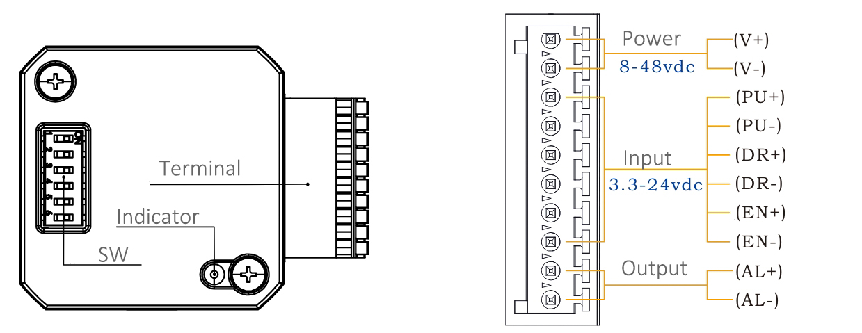
Terminal Definition
| Terminal | Name | Description | |
| 1 | V | 8-48VDC | |
| 2 | V- | GND | |
| 3 | X0 (PU ) | Optoelectronic isolation, differential, High level can directly receive 3.3-24VDC, with a minimum pulse width of 2us, The maximum pulse frequency is 400KHz, which can be used as a universal input port for Pulse/Direction | |
| 4 | X0-(PU-) | ||
| 5 | X1 (DR ) | ||
| 6 | X1-(DR-) | ||
| 7 | X2(EN ) | Optoelectronic isolation, differential, High level can directly receive 3.3-24VDC, with a minimum pulse width of 100us, The maximum pulse frequency is 10KHz, which can be used as a universal input port for Enable | |
| 8 | X2(EN-) | ||
| 9 | Y0 (AL ) | The default alarm output port can detect the driver alarm status and provide feedback to the main station. Other functions can be set through communication | |
| 10 | Y0-(AL-) | ||
Set Micro-step by SW1, SW2, SW3 and SW4: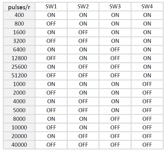
SW5=OFF: Pulse & Direction; SW=ON: Twin Pulse mode.
SW6=OFF: CW direction; SW6=ON: CCW direction.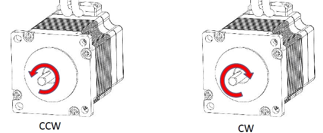
~~~~~~~~~~~~~~~~~~~~~~~~~~~~~~~~~~~~~~~~~~~~~~~~~~~~~~~~~~~~~~~~~~~~~~~~~~~~~~~~~~~~~~~~~
2. RS485 Type Integrated Stepper Motor, Terminal definition.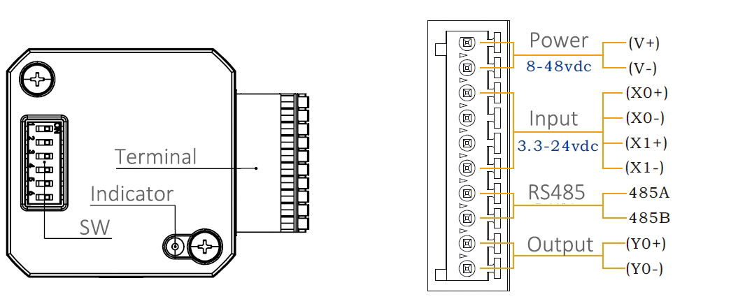
Terminal Definition
| Terminal | Name | Description | |
| 1 | V | 8-48VDC | |
| 2 | V- | GND | |
| 3 | X0 (PU ) | Optoelectronic isolation, differential, High level can directly receive 3.3-24VDC, with a minimum pulse width of 2us, The maximum pulse frequency is 400KHz, which can be used as a universal input port or a high-speed pulse input port | |
| 4 | X0-(PU-) | ||
| 5 | X1 (DR ) | ||
| 6 | X1-(DR-) | ||
| 7 | 485A(EN ) | RS485 Communication port, default baud rate is 115200, | |
| 8 | 485B(EN-) | ||
| 9 | Y0 (AL ) | The default alarm output port can detect the driver alarm status and provide feedback to the main station. Other functions can be set through communication | |
| 10 | Y0-(AL-) | ||
Set Device ID for RS485 integrated Stepper Motor by SW1 ~ SW5:
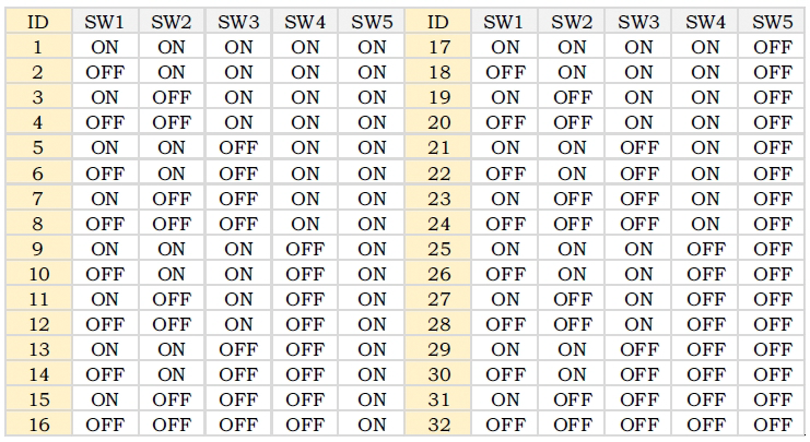
SW6 is used to set the terminal resistance; OFF=0 ohms; ON=120 ohms
CRC Check routine by C# :
Uint16 Funct_CRC16(unsigned char * puchMsg, Uint16 DataLen)
{
Uint16 i,j,tmp;
Uint16 crcdata=0xFFFF;
for(i=0;i<DataLen;i )
{
crcdata=(*puchMsg)^crcdata;
puchMsg ;
for(j=0;j<8;j )
{
tmp=crcdata&0x0001;
crcdata=crcdata>>1;
if(tmp){
crcdata=crcdata^0xA001;
}
}
}
returncrcdata;
}
Software Modbus Poll
Software Step-Config
1. Extract the zip file, open CommFile and Click Step-Config.exe
2. Right Click Modbus_485, and Click Property:
3. Click Property ComNN, Choose COM port, Baud rate and click Save and OK.
4. Start to use software control the RS485 Integrated stepper motor by below buttons:
RS485 Stepper Motor Controller Manual
Block Diagram:
2 Input signals can directly receive 3.3-24V DC levels at high levels, Max. frequency of 400KHZ.
X0: pulse input, IO start/stop, limit, direction, universal input.
X1 pulse input, IO start/stop, limit, direction, universal input.
...
1 Output signal, maximum withstand voltage 30V, maximum input or output current 30mA
Y0 : alarm output, universal output, and factory default alarm output.
LED indicator and status:

The IG23 series integrated motor is the perfect combination of drive and stepper motor,
which perfectly integrates stepper motor and drive technology, also built in 1000 line encoder,
it can save installation space, Simultaneously saving design and production costs,
supporting RS485 and TTL communication.
| Item | Specifications |
| Stepper Motor Size | NEMA23 |
| Encoder type | 1000 line encoder |
| Working voltage | 8-60VDC, Recommend DC36V |
| Driver Current | 0.5-5A |
| Velocity range | Up to 3000RPM |
| Control Method | RS485, Pulse& Direction, Twin-Pulse, I/O, Built-in Program |
| Torque value | 0.8 - 2.2Nm |
| Nonvolatile storage | Configuration parameters are stored in FLASH inside the MCU |
| DI and DO | 2 DI, 1 DO |
| Protection | Overvoltage, undervoltage, overcurrent, open winding, position deviation |
| Digital Input (2/3) | Receive 3.3-24VDC | ||
| Digital Output(1) | Maximum withstand voltage of 30V, | ||
| Maximum input or output current 30mA | |||
Motor Parameters
| Model No. | length mm L | Shaft length mm | Shaft dia. mm | Phase current A | Resistance Ω | inductance mH | Hold torque N.m | Inertia g.cm² | Weight g |
| IG2312 | 68 | 21 | 8 | 4 | 0.5 | 1.8 | 1.2 | 280 | 800 |
| IG2320 | 85 | 21 | 8 | 5 | 0.4 | 2.0 | 2.0 | 480 | 1100 |
Wiring Diagram:
~~~~~~~~~~~~~~~~~~~~~~~~~~~~~~~~~~~~~~~~~~~~~~~~~~~~~~~~~~~~~~~~~~~~~~~~~~~~~~~~~~~~~~~~~~~
1. Pulse Type Integrated Stepper Motor, Terminal definition.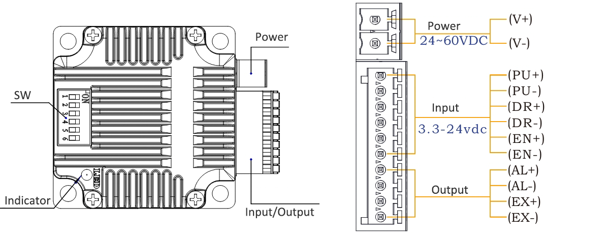
Terminal Definition
| Terminal | Name | Description | |
| 1 | V | 24~60VDC | |
| 2 | V- | GND | |
| 3 | X0 (PU ) | Optoelectronic isolation, differential, High level can directly receive 3.3-24VDC, with a minimum pulse width of 2us, The maximum pulse frequency is 400KHz, which can be used as a universal input port for Pulse/Direction | |
| 4 | X0-(PU-) | ||
| 5 | X1 (DR ) | ||
| 6 | X1-(DR-) | ||
| 7 | X2(EN ) | Optoelectronic isolation, differential, High level can directly receive 3.3-24VDC, with a minimum pulse width of 100us, The maximum pulse frequency is 10KHz, which can be used as a universal input port for Enable | |
| 8 | X2(EN-) | ||
| 9 | Y0 (AL ) | The default alarm output port can detect the driver alarm status and provide feedback to the main station. Other functions can be set through communication | |
| 10 | Y0-(AL-) | ||
| 11 | Y1(EX ) | The default In-place output , Other functions can be set through communication | |
| 12 | Y1(EX-) | ||
Set Micro-step by SW1, SW2, SW3 and SW4:
SW5=OFF: Pulse & Direction; SW=ON: Twin Pulse mode.
SW6=OFF: CW direction; SW6=ON: CCW direction.
~~~~~~~~~~~~~~~~~~~~~~~~~~~~~~~~~~~~~~~~~~~~~~~~~~~~~~~~~~~~~~~~~~~~~~~~~~~~~~~~~~~~~~~~~
2. RS485 Type Integrated Stepper Motor, Terminal definition.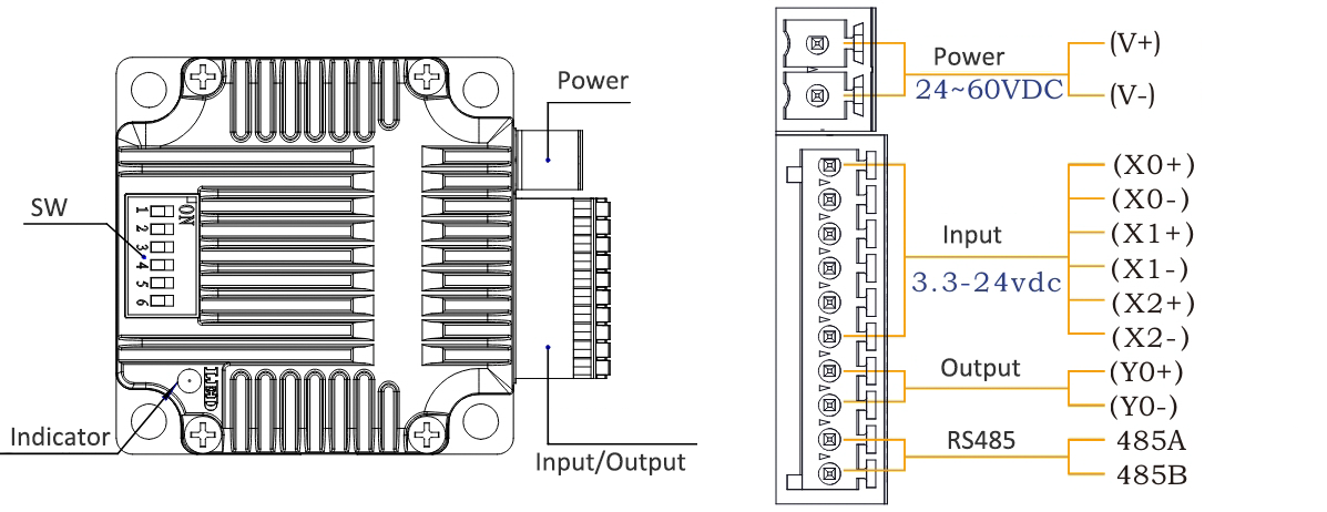
Terminal Definition
| Terminal | Name | Description | |
| 1 | V | 24~60VDC | |
| 2 | V- | GND | |
| 3 | X0 (PU ) | Optoelectronic isolation, differential, High level can directly receive 3.3-24VDC, with a minimum pulse width of 2us, The maximum pulse frequency is 400KHz, which can be used as a universal input port for Pulse/Direction/Enable | |
| 4 | X0-(PU-) | ||
| 5 | X1 (DR ) | ||
| 6 | X1-(DR-) | ||
| 7 | X2 (EN ) | ||
| 8 | X2-(EN-) | ||
| 9 | Y0 (AL ) | The default alarm output port can detect the driver alarm status and provide feedback to the main station. Other functions can be set through communication | |
| 10 | Y0-(AL-) | ||
| 11 | 485A | RS485 Communication port, default baud rate is 115200 | |
| 12 | 485B | ||
Set Device ID for RS485 integrated Stepper Motor by SW1 ~ SW5:
SW6 is used to set the terminal resistance; OFF=0 ohms; ON=120 ohms
CRC Check routine by C# :
Uint16 Funct_CRC16(unsigned char * puchMsg, Uint16 DataLen)
{
Uint16 i,j,tmp;
Uint16 crcdata=0xFFFF;
for(i=0;i<DataLen;i )
{
crcdata=(*puchMsg)^crcdata;
puchMsg ;
for(j=0;j<8;j )
{
tmp=crcdata&0x0001;
crcdata=crcdata>>1;
if(tmp){
crcdata=crcdata^0xA001;
}
}
}
returncrcdata;
}
Software Modbus Poll
Software Step-Config
1. Extract the zip file, open CommFile and Click Step-Config.exe
2. Right Click Modbus_485, and Click Property:
3. Click Property ComNN, Choose COM port, Baud rate and click Save and OK.
4. Start to use software control the RS485 Integrated stepper motor by below buttons:
RS485 Stepper Motor Controller Manual
Block Diagram:
2 Input signals can directly receive 3.3-24V DC levels at high levels, Max. frequency of 400KHZ.
X0: pulse input, IO start/stop, limit, direction, universal input.
X1 pulse input, IO start/stop, limit, direction, universal input.
...
1 Output signal, maximum withstand voltage 30V, maximum input or output current 30mA
Y0 : alarm output, universal output, and factory default alarm output.
LED indicator and status:

The IG23 series integrated motor is the perfect combination of drive and stepper motor,
which perfectly integrates stepper motor and drive technology, also built in 1000 line encoder,
it can save installation space, Simultaneously saving design and production costs,
supporting RS485 and TTL communication.
| Item | Specifications |
| Stepper Motor Size | NEMA24 |
| Encoder type | 1000 line encoder |
| Working voltage | 24-60VDC |
| Driver Current | 0.5-5A |
| Velocity range | Up to 3000RPM |
| Control Method | RS485, Pulse& Direction, Twin-Pulse, I/O, Built-in Program |
| Torque value | 1.6 - 3.5Nm |
| Nonvolatile storage | Configuration parameters are stored in FLASH inside the MCU |
| DI and DO | 2 DI, 1 DO |
| Protection | Overvoltage, undervoltage, overcurrent, open winding, position deviation |
| Digital Input (2/3) | Receive 3.3-24VDC | ||
| Digital Output(1) | Maximum withstand voltage of 30V, | ||
| Maximum input or output current 30mA | |||
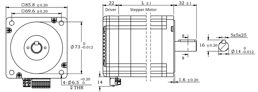
Motor Parameters
| Model No. | length mm L | Shaft length mm | Shaft dia. mm | Phase current A | Resistance Ω | inductance mH | Hold torque N.m | Inertia g.cm² | Weight g |
| IG2422 | 68 | 21 | 8 | 5 | 0.33 | 1.05 | 2.2 | 490 | 1300 |
| IG2430 | 85 | 21 | 8 | 5 | 0.43 | 2.0 | 3.0 | 690 | 1500 |
Wiring Diagram:
~~~~~~~~~~~~~~~~~~~~~~~~~~~~~~~~~~~~~~~~~~~~~~~~~~~~~~~~~~~~~~~~~~~~~~~~~~~~~~~~~~~~~~~~~~~
1. Pulse Type Integrated Stepper Motor, Terminal definition.
Terminal Definition
| Terminal | Name | Description | |
| 1 | V | 24~60VDC | |
| 2 | V- | GND | |
| 3 | X0 (PU ) | Optoelectronic isolation, differential, High level can directly receive 3.3-24VDC, with a minimum pulse width of 2us, The maximum pulse frequency is 400KHz, which can be used as a universal input port for Pulse/Direction | |
| 4 | X0-(PU-) | ||
| 5 | X1 (DR ) | ||
| 6 | X1-(DR-) | ||
| 7 | X2(EN ) | Optoelectronic isolation, differential, High level can directly receive 3.3-24VDC, with a minimum pulse width of 100us, The maximum pulse frequency is 10KHz, which can be used as a universal input port for Enable | |
| 8 | X2(EN-) | ||
| 9 | Y0 (AL ) | The default alarm output port can detect the driver alarm status and provide feedback to the main station. Other functions can be set through communication | |
| 10 | Y0-(AL-) | ||
| 11 | Y1(EX ) | The default In-place output , Other functions can be set through communication | |
| 12 | Y1(EX-) | ||
Set Micro-step by SW1, SW2, SW3 and SW4:
SW5=OFF: Pulse & Direction; SW=ON: Twin Pulse mode.
SW6=OFF: CW direction; SW6=ON: CCW direction.
~~~~~~~~~~~~~~~~~~~~~~~~~~~~~~~~~~~~~~~~~~~~~~~~~~~~~~~~~~~~~~~~~~~~~~~~~~~~~~~~~~~~~~~~~
2. RS485 Type Integrated Stepper Motor, Terminal definition.
Terminal Definition
| Terminal | Name | Description | |
| 1 | V | 24~60VDC | |
| 2 | V- | GND | |
| 3 | X0 (PU ) | Optoelectronic isolation, differential, High level can directly receive 3.3-24VDC, with a minimum pulse width of 2us, The maximum pulse frequency is 400KHz, which can be used as a universal input port for Pulse/Direction/Enable | |
| 4 | X0-(PU-) | ||
| 5 | X1 (DR ) | ||
| 6 | X1-(DR-) | ||
| 7 | X2 (EN ) | ||
| 8 | X2-(EN-) | ||
| 9 | Y0 (AL ) | The default alarm output port can detect the driver alarm status and provide feedback to the main station. Other functions can be set through communication | |
| 10 | Y0-(AL-) | ||
| 11 | 485A | RS485 Communication port, default baud rate is 115200 | |
| 12 | 485B | ||
Set Device ID for RS485 integrated Stepper Motor by SW1 ~ SW5:
SW6 is used to set the terminal resistance; OFF=0 ohms; ON=120 ohms
CRC Check routine by C# :
Uint16 Funct_CRC16(unsigned char * puchMsg, Uint16 DataLen)
{
Uint16 i,j,tmp;
Uint16 crcdata=0xFFFF;
for(i=0;i<DataLen;i )
{
crcdata=(*puchMsg)^crcdata;
puchMsg ;
for(j=0;j<8;j )
{
tmp=crcdata&0x0001;
crcdata=crcdata>>1;
if(tmp){
crcdata=crcdata^0xA001;
}
}
}
returncrcdata;
}
Software Modbus Poll
Software Step-Config
1. Extract the zip file, open CommFile and Click Step-Config.exe
2. Right Click Modbus_485, and Click Property:
3. Click Property ComNN, Choose COM port, Baud rate and click Save and OK.
4. Start to use software control the RS485 Integrated stepper motor by below buttons:
RS485 Stepper Motor Controller Manual
Block Diagram:
2 Input signals can directly receive 3.3-24V DC levels at high levels, Max. frequency of 400KHZ.
X0: pulse input, IO start/stop, limit, direction, universal input.
X1 pulse input, IO start/stop, limit, direction, universal input.
...
1 Output signal, maximum withstand voltage 30V, maximum input or output current 30mA
Y0 : alarm output, universal output, and factory default alarm output.
LED indicator and status:
The IG23 series integrated motor is the perfect combination of drive and stepper motor,
which perfectly integrates stepper motor and drive technology, also built in 1000 line encoder,
it can save installation space, Simultaneously saving design and production costs,
supporting RS485 and TTL communication.
| Item | Specifications |
| Stepper Motor Size | NEMA34 |
| Encoder type | 1000 line encoder |
| Working voltage | 24~80VDC, 18~60VAC |
| Driver Current | 0.5-6.5A |
| Velocity range | Up to 3000RPM |
| Control Method | RS485, Pulse& Direction, Twin-Pulse, I/O, Built-in Program |
| Torque value | 3.5 -12.5Nm |
| Nonvolatile storage | Configuration parameters are stored in FLASH inside the MCU |
| DI and DO | 2 DI, 1 DO |
| Protection | Overvoltage, undervoltage, overcurrent, open winding, position deviation |
| Digital Input (2/3) | Receive 3.3-24VDC | ||
| Digital Output(1) | Maximum withstand voltage of 30V, | ||
| Maximum input or output current 30mA | |||
Motor Parameters
| Model No. | length mm L | Shaft length mm | Shaft dia. mm | Phase current A | Resistance Ω | inductance mH | Hold torque N.m | Inertia g.cm² | Weight g |
| IG3445 | 80 | 32 | 14 | 6 | 0.5 | 3.6 | 4.5 | 1950 | 2900 |
| IG23465 | 98 | 32 | 14 | 6 | 0.63 | 4.5 | 6.5 | 2500 | 3400 |
| IG3485 | 118 | 32 | 14 | 6 | 0.5 | 4.2 | 8.5 | 2800 | 4100 |
| IG34125 | 151 | 32 | 14 | 6 | 0.63 | 4.7 | 12.5 | 4950 | 5600 |
Wiring Diagram:
~~~~~~~~~~~~~~~~~~~~~~~~~~~~~~~~~~~~~~~~~~~~~~~~~~~~~~~~~~~~~~~~~~~~~~~~~~~~~~~~~~~~~~~~~~~
1. Pulse Type Integrated Stepper Motor, Terminal definition.
Terminal Definition
| Terminal | Name | Description | |
| 1 | V | 24~60VDC | |
| 2 | V- | GND | |
| 3 | X0 (PU ) | Optoelectronic isolation, differential, High level can directly receive 3.3-24VDC, with a minimum pulse width of 2us, The maximum pulse frequency is 400KHz, which can be used as a universal input port for Pulse/Direction | |
| 4 | X0-(PU-) | ||
| 5 | X1 (DR ) | ||
| 6 | X1-(DR-) | ||
| 7 | X2(EN ) | Optoelectronic isolation, differential, High level can directly receive 3.3-24VDC, with a minimum pulse width of 100us, The maximum pulse frequency is 10KHz, which can be used as a universal input port for Enable | |
| 8 | X2(EN-) | ||
| 9 | Y0 (AL ) | The default alarm output port can detect the driver alarm status and provide feedback to the main station. Other functions can be set through communication | |
| 10 | Y0-(AL-) | ||
| 11 | Y1(EX ) | The default In-place output , Other functions can be set through communication | |
| 12 | Y1(EX-) | ||
Set Micro-step by SW1, SW2, SW3 and SW4:
SW5=OFF: Pulse & Direction; SW=ON: Twin Pulse mode.
SW6=OFF: CW direction; SW6=ON: CCW direction.
~~~~~~~~~~~~~~~~~~~~~~~~~~~~~~~~~~~~~~~~~~~~~~~~~~~~~~~~~~~~~~~~~~~~~~~~~~~~~~~~~~~~~~~~~
2. RS485 Type Integrated Stepper Motor, Terminal definition.
Terminal Definition
| Terminal | Name | Description | |
| 1 | V | 24~60VDC | |
| 2 | V- | GND | |
| 3 | X0 (PU ) | Optoelectronic isolation, differential, High level can directly receive 3.3-24VDC, with a minimum pulse width of 2us, The maximum pulse frequency is 400KHz, which can be used as a universal input port for Pulse/Direction | |
| 4 | X0-(PU-) | ||
| 5 | X1 (DR ) | ||
| 6 | X1-(DR-) | ||
| 7 | X2 (EN ) | ||
| 8 | X2-(EN-) | ||
| 9 | Y0 (AL ) | The default alarm output port can detect the driver alarm status and provide feedback to the main station. Other functions can be set through communication | |
| 10 | Y0-(AL-) | ||
| 11 | 485A | RS485 Communication port, default baud rate is 115200 | |
| 12 | 485B | ||
Set Device ID for RS485 integrated Stepper Motor by SW1 ~ SW5:
SW6 is used to set the terminal resistance; OFF=0 ohms; ON=120 ohms
CRC Check routine by C# :
Uint16 Funct_CRC16(unsigned char * puchMsg, Uint16 DataLen)
{
Uint16 i,j,tmp;
Uint16 crcdata=0xFFFF;
for(i=0;i<DataLen;i )
{
crcdata=(*puchMsg)^crcdata;
puchMsg ;
for(j=0;j<8;j )
{
tmp=crcdata&0x0001;
crcdata=crcdata>>1;
if(tmp){
crcdata=crcdata^0xA001;
}
}
}
returncrcdata;
}
Software Modbus Poll
Software Step-Config
1. Extract the zip file, open CommFile and Click Step-Config.exe
2. Right Click Modbus_485, and Click Property:
3. Click Property ComNN, Choose COM port, Baud rate and click Save and OK.
4. Start to use software control the RS485 Integrated stepper motor by below buttons:
RS485 Stepper Motor Controller Manual
Block Diagram:
2 Input signals can directly receive 3.3-24V DC levels at high levels, Max. frequency of 400KHZ.
X0: pulse input, IO start/stop, limit, direction, universal input.
X1 pulse input, IO start/stop, limit, direction, universal input.
...
1 Output signal, maximum withstand voltage 30V, maximum input or output current 30mA
Y0 : alarm output, universal output, and factory default alarm output.
LED indicator and status:

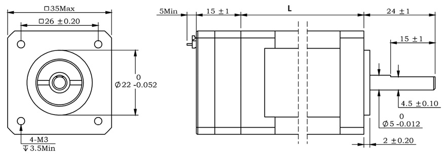
The IG14 series integrated motor is the perfect combination of drive and stepper motor,
which perfectly integrates stepper motor and drive technology, also built in 1000 line encoder,
it can save installation space, Simultaneously saving design and production costs,
supporting RS485 and TTL communication.
| Item | Specifications |
| Stepper Motor Size | NEMA14 |
| Encoder type | 1000 line encoder |
| Working voltage | 8 ~ 36VDC |
| Driver Current | 0.2-2.0A |
| Velocity range | Up to 3000RPM |
| Control Method | RS485, Pulse& Direction, Twin-Pulse, I/O, Built-in Program |
| Torque value | 0.2 - 0.4Nm |
| Nonvolatile storage | Configuration parameters are stored in FLASH inside the MCU |
| DI and DO | 2/3 DI, 1 DO |
| Protection | Overvoltage, undervoltage, overcurrent, open winding, position deviation |
| Digital Input (2/3) | Receive 3.3-24VDC | ||
| Digital Output(1) | Maximum withstand voltage of 30V, | ||
| Maximum input or output current 30mA | |||
Motor Parameters
Pulse type NEMA14 integrated Stepper Motor:
| Model No. | length mm L | Shaft length mm | Shaft dia. mm | Phase current A | Resistance Ω | inductance mH | Hold torque N.m | Inertia g.cm² | Weight g |
| IG1418 | 32 | 24 | 5 | 1.5 | 1.5 | 1.6 | 0.18 | 15 | 200 |
| IG1425 | 37 | 24 | 5 | 1.5 | 1.5 | 2.0 | 0.25 | 26 | 250 |
| IG1440 | 50 | 24 | 5 | 1.8 | 1.1 | 2.5 | 0.40 | 38 | 350 |
RS485 type NEMA14 integrated Stepper Motor:
| Model No. | length mm L | Shaft length mm | Shaft dia. mm | Phase current A | Resistance Ω | inductance mH | Hold torque N.m | Inertia g.cm² | Weight g |
| IG1412 | 26 | 24 | 5 | 1.0 | 1.5 | 1.9 | 0.12 | 8 | 230 |
| IG1420 | 34 | 24 | 5 | 1.5 | 2.1 | 2.1 | 0.20 | 14 | 290 |
| IG1425 | 40 | 24 | 5 | 1.5 | 2.5 | 2.8 | 0.25 | 20 | 340 |
| IG1435 | 53 | 24 | 5 | 1.8 | 2.9 | 4.8 | 0.35 | 31 | 440 |
Wiring Diagram:
~~~~~~~~~~~~~~~~~~~~~~~~~~~~~~~~~~~~~~~~~~~~~~~~~~~~~~~~~~~~~~~~~~~~~~~~~~~~~~~~~~~~~~~~~~~
1. Pulse Type Integrated Stepper Motor, Terminal definition.
Terminal Definition
| Terminal | Name | Description | |
| 1 | V | 8-48VDC | |
| 2 | V- | GND | |
| 3 | X0 (PU ) | Optoelectronic isolation, differential, High level can directly receive 3.3-24VDC, with a minimum pulse width of 2us, The maximum pulse frequency is 400KHz, which can be used as a universal input port for Pulse/Direction | |
| 4 | X0-(PU-) | ||
| 5 | X1 (DR ) | ||
| 6 | X1-(DR-) | ||
| 7 | X2(EN ) | Optoelectronic isolation, differential, High level can directly receive 3.3-24VDC, with a minimum pulse width of 100us, The maximum pulse frequency is 10KHz, which can be used as a universal input port for Enable | |
| 8 | X2(EN-) | ||
| 9 | Y0 (AL ) | The default alarm output port can detect the driver alarm status and provide feedback to the main station. Other functions can be set through communication | |
| 10 | Y0-(AL-) | ||
| 11 | Y1 | Default function is in-place output | |
| 12 | Y1- | ||
~~~~~~~~~~~~~~~~~~~~~~~~~~~~~~~~~~~~~~~~~~~~~~~~~~~~~~~~~~~~~~~~~~~~~~~~~~~~~~~~~~~~~~~~~
2. RS485 Type Integrated Stepper Motor, Terminal definition.
Terminal Definition
| Terminal | Name | Description | |
| 1 | V | 8-48VDC | |
| 2 | V- | GND | |
| 3 | X0 (PU ) | Optoelectronic isolation, differential, High level can directly receive 3.3-24VDC, with a minimum pulse width of 2us, The maximum pulse frequency is 400KHz, which can be used as a universal input port or a high-speed pulse input port | |
| 4 | X0-(PU-) | ||
| 5 | X1 (DR ) | ||
| 6 | X1-(DR-) | ||
| 7 | X2 | ||
| 8 | X2- | ||
| 9 | Y0 (AL ) | The default alarm output port can detect the driver alarm status and provide feedback to the main station. Other functions can be set through communication | |
| 10 | Y0-(AL-) | ||
| 11 | 485A | RS485 Communication port, default baud rate is 115200, | |
| 12 | 485B | ||
CRC Check routine by C# :
Uint16 Funct_CRC16(unsigned char * puchMsg, Uint16 DataLen)
{
Uint16 i,j,tmp;
Uint16 crcdata=0xFFFF;
for(i=0;i<DataLen;i )
{
crcdata=(*puchMsg)^crcdata;
puchMsg ;
for(j=0;j<8;j )
{
tmp=crcdata&0x0001;
crcdata=crcdata>>1;
if(tmp){
crcdata=crcdata^0xA001;
}
}
}
returncrcdata;
}
Software Modbus Poll
Software Step-Config
1. Extract the zip file, open CommFile and Click Step-Config.exe
2. Right Click Modbus_485, and Click Property:
3. Click Property ComNN, Choose COM port, Baud rate and click Save and OK.
4. Start to use software control the RS485 Integrated stepper motor by below buttons:
RS485 Stepper Motor Controller Manual
Block Diagram:
2 Input signals can directly receive 3.3-24V DC levels at high levels, Max. frequency of 400KHZ.
X0: pulse input, IO start/stop, limit, direction, universal input.
X1 pulse input, IO start/stop, limit, direction, universal input.
...
1 Output signal, maximum withstand voltage 30V, maximum input or output current 30mA
Y0 : alarm output, universal output, and factory default alarm output.
LED indicator and status:

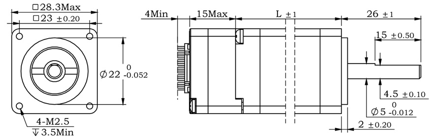
The IG11 series integrated motor is the perfect combination of drive and stepper motor,
which perfectly integrates stepper motor and drive technology, also built in 1000 line encoder,
it can save installation space, Simultaneously saving design and production costs,
supporting RS485 and TTL communication.
| Item | Specifications |
| Stepper Motor Size | NEMA11 |
| Encoder type | 1000 line encoder |
| Working voltage | 8~36VDC |
| Driver Current | 0.2-2.0A |
| Velocity range | Up to 3000RPM |
| Control Method | RS485, Pulse& Direction, Twin-Pulse, I/O, Built-in Program |
| Torque value | 0.08 - 0.24Nm |
| Nonvolatile storage | Configuration parameters are stored in FLASH inside the MCU |
| DI and DO | 2/3 DI, 1 DO |
| Protection | Overvoltage, undervoltage, overcurrent, open winding, position deviation |
| Digital Input (2/3) | Receive 3.3-24VDC | ||
| Digital Output(1) | Maximum withstand voltage of 30V, | ||
| Maximum input or output current 30mA | |||
Motor Parameters
NEMA11 integrated Stepper Motor:
| Model No. | length mm L | Shaft length mm | Shaft dia. mm | Phase current A | Resistance Ω | inductance mH | Hold torque N.m | Inertia g.cm² | Weight g |
| IG11008 | 31 | 26 | 5 | 1.0 | 1.5 | 1.1 | 0.08 | 9 | 115 |
| IG11018 | 52 | 26 | 5 | 1.3 | 2.4 | 2.3 | 0.18 | 18 | 205 |
| IG11024 | 63 | 26 | 5 | 1.5 | 1.8 | 2.1 | 0.24 | 30 | 268 |
Wiring Diagram:
~~~~~~~~~~~~~~~~~~~~~~~~~~~~~~~~~~~~~~~~~~~~~~~~~~~~~~~~~~~~~~~~~~~~~~~~~~~~~~~~~~~~~~~~~~~
1. Pulse Type Integrated Stepper Motor, Terminal definition.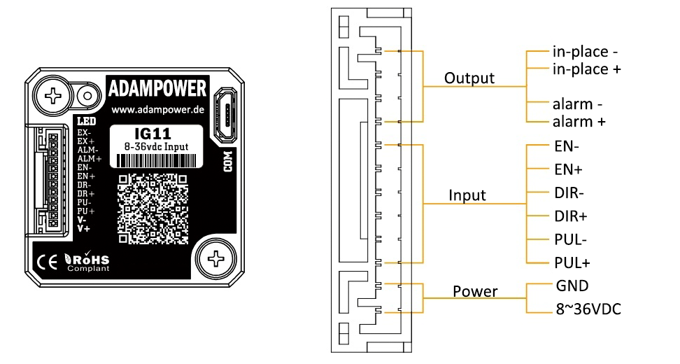
Terminal Definition
| Terminal | Name | Description | |
| 1 | V | 8-36VDC | |
| 2 | V- | GND | |
| 3 | X0 (PU ) | Optoelectronic isolation, differential, High level can directly receive 3.3-24VDC, with a minimum pulse width of 2us, The maximum pulse frequency is 400KHz, which can be used as a universal input port for Pulse/Direction | |
| 4 | X0-(PU-) | ||
| 5 | X1 (DR ) | ||
| 6 | X1-(DR-) | ||
| 7 | X2(EN ) | Optoelectronic isolation, differential, High level can directly receive 3.3-24VDC, with a minimum pulse width of 100us, The maximum pulse frequency is 10KHz, which can be used as a universal input port for Enable | |
| 8 | X2(EN-) | ||
| 9 | Y0 (AL ) | The default alarm output port can detect the driver alarm status and provide feedback to the main station. Other functions can be set through communication | |
| 10 | Y0-(AL-) | ||
| 11 | Y1 | Default function is in-place output | |
| 12 | Y1- | ||
~~~~~~~~~~~~~~~~~~~~~~~~~~~~~~~~~~~~~~~~~~~~~~~~~~~~~~~~~~~~~~~~~~~~~~~~~~~~~~~~~~~~~~~~~
2. RS485 Type Integrated Stepper Motor, Terminal definition.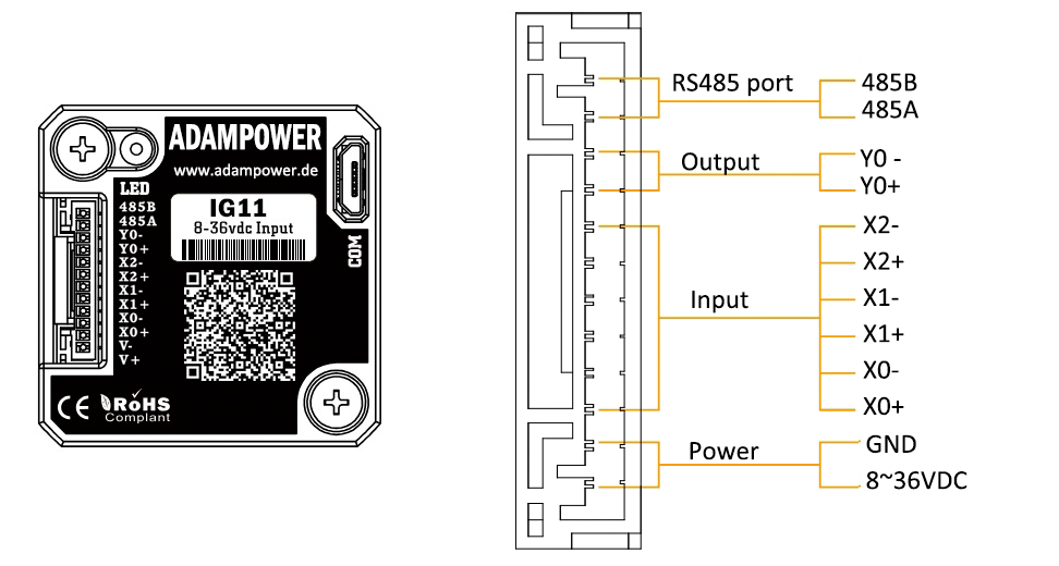
Terminal Definition
| Terminal | Name | Description | |
| 1 | V | 8-36VDC | |
| 2 | V- | GND | |
| 3 | X0 (PU ) | Optoelectronic isolation, differential, High level can directly receive 3.3-24VDC, with a minimum pulse width of 2us, The maximum pulse frequency is 400KHz, which can be used as a universal input port or a high-speed pulse input port | |
| 4 | X0-(PU-) | ||
| 5 | X1 (DR ) | ||
| 6 | X1-(DR-) | ||
| 7 | X2(EN ) | ||
| 8 | X2-(EN-) | ||
| 9 | Y0 (AL ) | The default alarm output port can detect the driver alarm status and provide feedback to the main station. Other functions can be set through communication | |
| 10 | Y0-(AL-) | ||
| 11 | 485A | RS485 Communication port, default baud rate is 115200, | |
| 12 | 485B | ||
CRC Check routine by C# :
Uint16 Funct_CRC16(unsigned char * puchMsg, Uint16 DataLen)
{
Uint16 i,j,tmp;
Uint16 crcdata=0xFFFF;
for(i=0;i<DataLen;i )
{
crcdata=(*puchMsg)^crcdata;
puchMsg ;
for(j=0;j<8;j )
{
tmp=crcdata&0x0001;
crcdata=crcdata>>1;
if(tmp){
crcdata=crcdata^0xA001;
}
}
}
returncrcdata;
}
Software Modbus Poll
Software Step-Config
1. Extract the zip file, open CommFile and Click Step-Config.exe
2. Right Click Modbus_485, and Click Property:
3. Click Property ComNN, Choose COM port, Baud rate and click Save and OK.
4. Start to use software control the RS485 Integrated stepper motor by below buttons:
RS485 Stepper Motor Controller Manual
Block Diagram:
2 Input signals can directly receive 3.3-24V DC levels at high levels, Max. frequency of 400KHZ.
X0: pulse input, IO start/stop, limit, direction, universal input.
X1 pulse input, IO start/stop, limit, direction, universal input.
...
1 Output signal, maximum withstand voltage 30V, maximum input or output current 30mA
Y0 : alarm output, universal output, and factory default alarm output.
LED indicator and status:
The IG6 series integrated motor is the perfect combination of drive and stepper motor,
which perfectly integrates stepper motor and drive technology, also built in 1000 line encoder,
it can save installation space, Simultaneously saving design and production costs,
supporting RS485 and TTL communication.
| Item | Specifications |
| Stepper Motor Size | NEMA8 |
| Encoder type | 1000 line encoder |
| Working voltage | 6~24VDC |
| Driver Current | 0.2-1.5A |
| Velocity range | Up to 3000RPM |
| Control Method | RS485, Pulse& Direction, Twin-Pulse, I/O, Built-in Program |
| Torque value | 0.08 - 0.24Nm |
| Nonvolatile storage | Configuration parameters are stored in FLASH inside the MCU |
| DI and DO | 2/3 DI, 1 DO |
| Protection | Overvoltage, undervoltage, overcurrent, open winding, position deviation |
| Digital Input (2/3) | Receive 3.3-24VDC | ||
| Digital Output(1) | Maximum withstand voltage of 30V, | ||
| Maximum input or output current 30mA | |||
Motor Parameters
NEMA11 integrated Stepper Motor:
| Model No. | length mm L | Shaft length mm | Shaft dia. mm | Phase current A | Resistance Ω | inductance mH | Hold torque N.m | Inertia g.cm² | Weight g |
| IG8002 | 28 | 18 | 4 | 0.6 | 6 | 3 | 0.015 | 2.5 | 80 |
| IG8004 | 38 | 18 | 4 | 1.0 | 3.2 | 1.3 | 0.04 | 3.3 | 100 |
Wiring Diagram:
~~~~~~~~~~~~~~~~~~~~~~~~~~~~~~~~~~~~~~~~~~~~~~~~~~~~~~~~~~~~~~~~~~~~~~~~~~~~~~~~~~~~~~~~~~~
1. Pulse Type NEMA6 Integrated Stepper Motor, Terminal definition.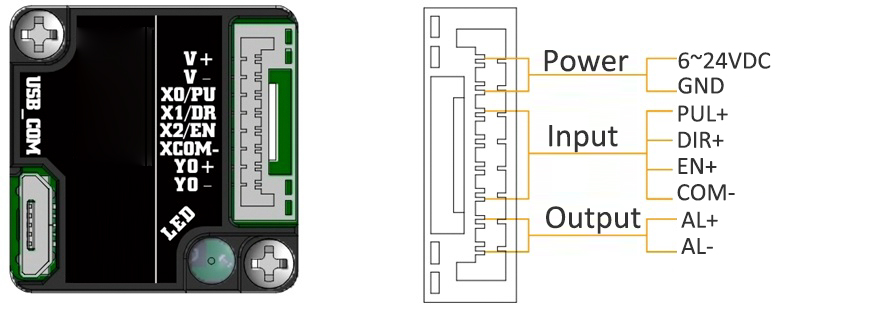
~~~~~~~~~~~~~~~~~~~~~~~~~~~~~~~~~~~~~~~~~~~~~~~~~~~~~~~~~~~~~~~~~~~~~~~~~~~~~~~~~~~~~~~~~
2. TTL Type NEMA11 Integrated Stepper Motor, Terminal definition.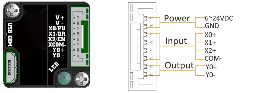
Terminal Definition
| Terminal | Name | Description | |
| 1 | V | 6 ~ 24VDC | |
| 2 | V- | GND | |
| 3 | X0(PU) | Optoelectronic isolation, differential, High level can directly receive 3.3-24VDC, with a minimum pulse width of 2us, The maximum pulse frequency is 400KHz, which can be used as a universal input port Pulse/Direction | |
| 4 | X1(DR) | ||
| 5 | X2(EN) | Optoelectronic isolation, differential, High level can directly receive 3.3-24VDC, with a minimum pulse width of 100us, The maximum pulse frequency is 10KHz, which can be used as a universal input port for Enable | |
| 6 | COM- | Input common ground | |
| 7 | Y0 (AL ) | The default alarm output port can detect the driver alarm status and provide feedback to the main station. Other functions can be set through communication | |
| 8 | Y0-(AL-) | ||
Block Diagram:
2 Input signals can directly receive 3.3-24V DC levels at high levels, Max. frequency of 400KHZ.
X0: pulse input, IO start/stop, limit, direction, universal input.
X1 pulse input, IO start/stop, limit, direction, universal input.
...
1 Output signal, maximum withstand voltage 30V, maximum input or output current 30mA
Y0 : alarm output, universal output, and factory default alarm output.
LED indicator and status:

AR42 is a high-integrated and compact size stepper driver. It adopts standard RS485 communication
protocol, can be connected with PLC, HMI, industrial computer and other upper computer with only two
communication lines. Up to 32 axes of motion platform networking can be achieved with its built-in motion
control commands.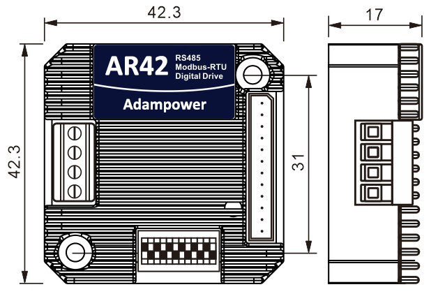
AR42 can be set to 1-256 subdivisions and adopts built-in micro-subdivision technology, which can achieve
high subdivision effects even under low subdivision conditions, ensuring that the motor operates with uniform
step intervals and no large or small step problems.
Can be set between 1-256 subdivisions, with uniform motor step spacing; Stable output at 1/12 rpm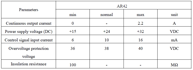
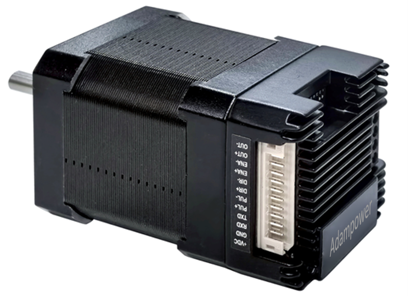
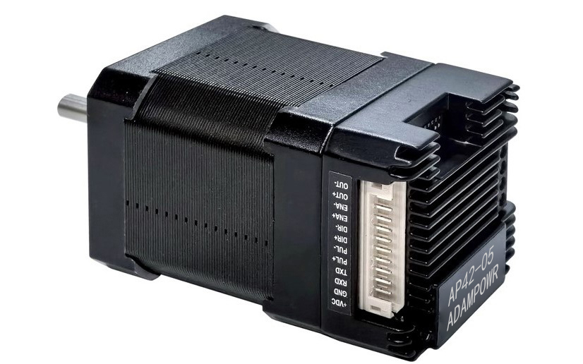
AR42 is designed for NEMA17 stepper motor, The NEMA17 integrated stepper motor with
torque 0.35, 0.50 and 0.7Nm:
| Model No. | Holding Torque(Nm) | Motor Length(mm) | Encoder Type |
| AR42-03 | 0.35 | 40 | 1000 line Encoder, Magnetic or Optoelectronic |
| AR42-05 | 0.50 | 48 | |
| AR42-07 | 0.70 | 60 |
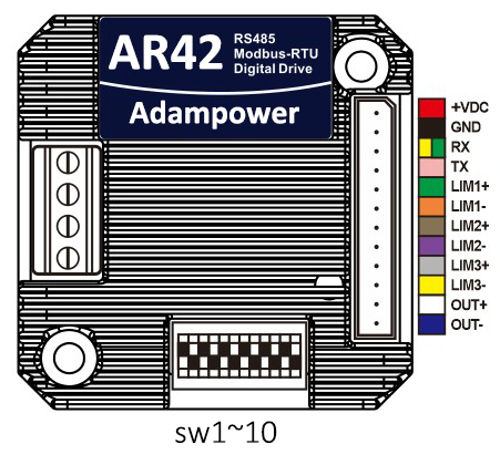
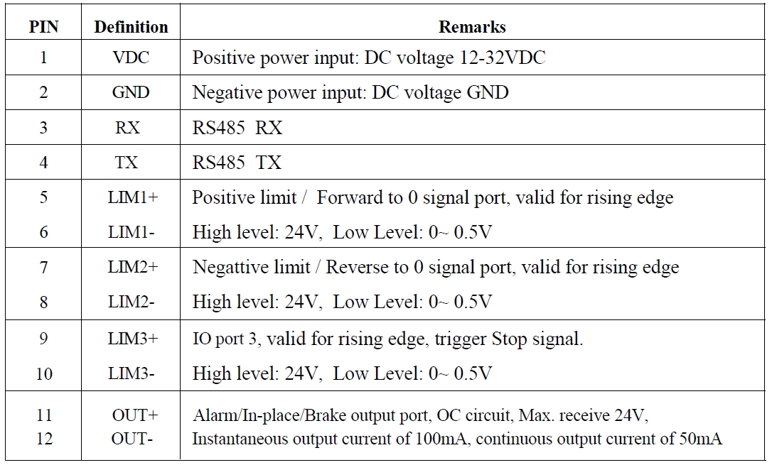
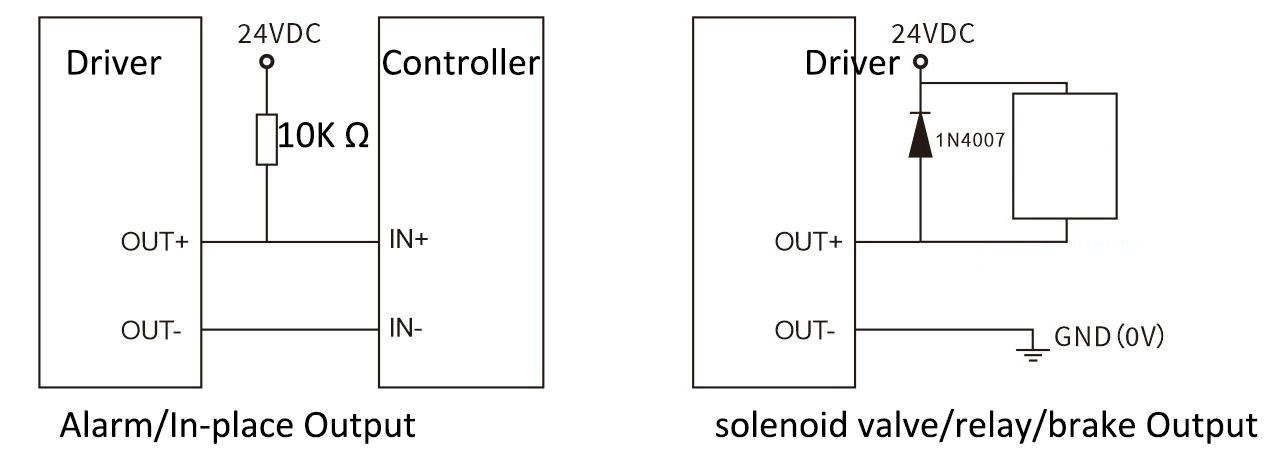
Port Definition
OUT /OUT- as defferential output port, Max.receive voltage is DC24V, and instaneous ouput
current is 100mA, continuous output current is 50mA.
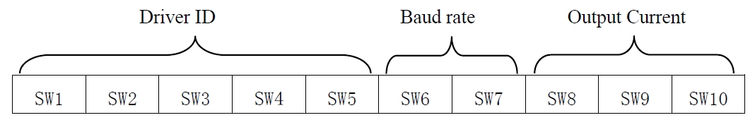
Set ID address, Baud Rate and Ouptut current by SW1~SW10:
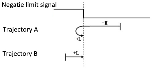
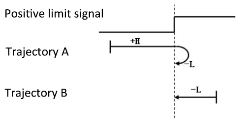
Zero-return function with two trajectory A and when limit signal is triggered and not:
AR42 Modbus Stepper Motor Controller User Manual
Software Modbus Poll
AdamPower Software
More Information on detail, please feel free to contact me


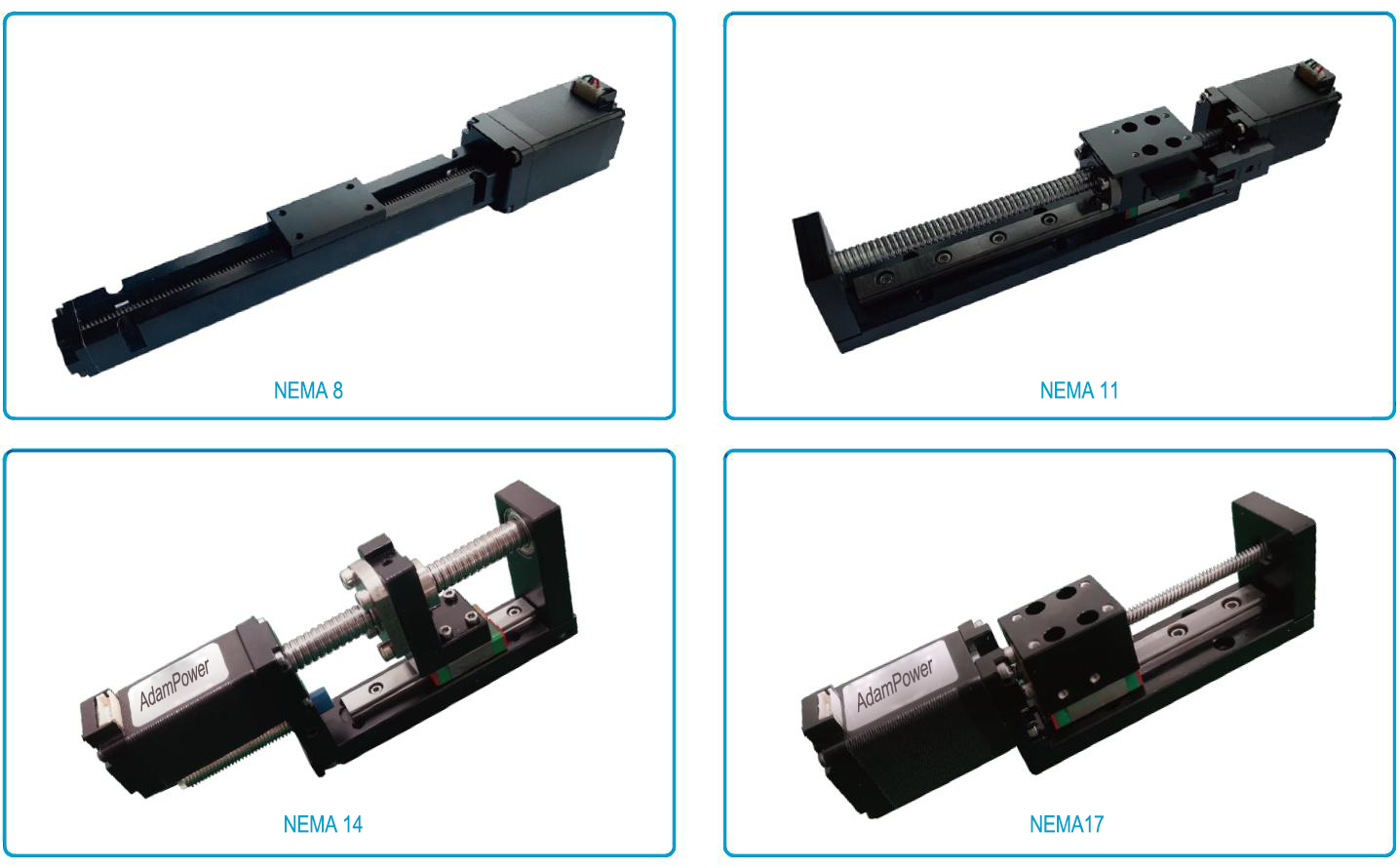
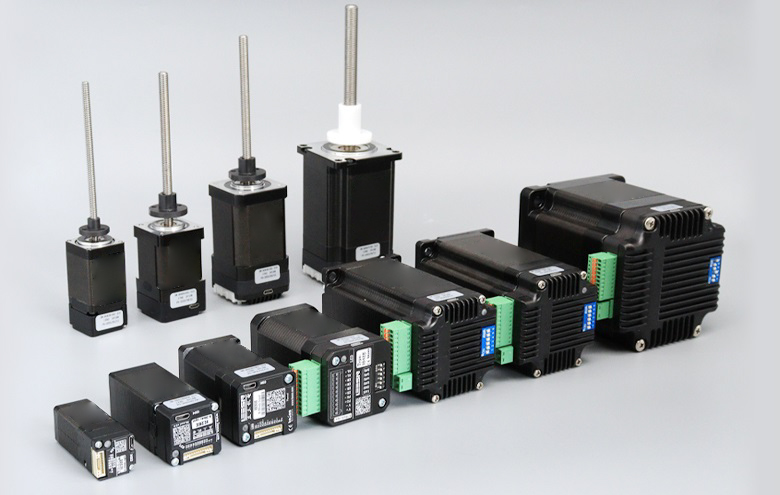
Size:
NEMA6, NEMA8, NEMA11, NEMA14, NEMA17, NEMA23, NEMA23, NEMA34
14mm, 20mm, 28mm, 35mm, 42mm, 57mm, 60mm, 86mm
Stepper
0.001524mm~0.16mm
Performance
Maximum thrust up to 240kg, low temperature rise, low vibration, low noise,
long life (up to 5 million cycles), and high positioning accuracy (up to ±0.005 mm)
Application
Medical diagnostic equipment, life science instruments, robots, optical equipment,
analytical instruments, semiconductor equipment, communication equipment, automation equipment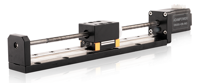
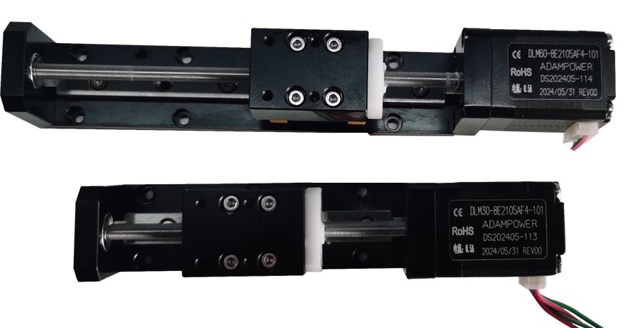
NEMA8 Lead Screw Linear Actuators
Linear Module, Linear Slider
| Motor Type | Bipolar stepper |
| Step Angle | 1.8° |
| Voltage (V) | 2.5 / 6.3 |
| Current (A) | 0.5 |
| Resistance (Ohms) | 5.1 / 12.5 |
| Inductance (mH) | 1.5 / 4.5 |
| Lead Wires | 4 |
| Motor Length (mm) | 30 / 42 |
| Stroke (mm) | 30 / 60 / 90 |
| Ambient Temperature | -20℃ ~ 50℃ |
| Temperature Rise | 80K Max. |
| Dielectric Strength | 1mA Max. @ 500V, 1KHz, 1Sec. |
| Insulation Resistance | 100MΩ Min. @500Vdc |
Motor Characteristics:
| Motor | Phase voltage [V] | Phase Current [A] | Phase Resistance [Ω] | Phase Inductance [mH] | Lenght [mm] | Number of lead Wires |
|---|---|---|---|---|---|---|
| 08S | 2.5 | 0.5 | 5.1 | 1.5 | 27.2 | 4 |
| 08D | 4.4 | 0.5 | 8.8 | 2.7 | 38.1 | 4 |
0830/0842:
Motor | Voltage/ Phase (V) | Current/ Phase (A) | Resistance/ Phase (Ω) | Inductance/ Phase (mH) | Number of Lead Wires | Rotor Inertia (g.cm2) | Motor Weight (g) | Motor Length L (mm) |
0830 | 2.5 | 0.5 | 5.1 | 1.5 | 4 | 2 | 50 | 30 |
0842 | 6.3 | 0.5 | 12.5 | 4.5 | 4 | 3 | 80 | 42 |
Available Lead Screw and Travel per Step:
Diameter (mm) | Lead (mm) | Step (mm) | Power off self-locking force (N) |
3.5 | 0.3048 | 0.001524 | 80 |
3.5 | 1 | 0.005 | 40 |
3.5 | 2 | 0.01 | 10 |
3.5 | 4 | 0.02 | 1 |
3.5 | 8 | 0.04 | 0 |
3.5 | Customized size | ||
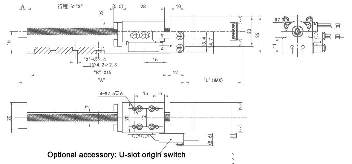
08S/08D Linear Actuator outline drawing:

| Stroke B (mm) | 20 | 40 | 60 | 80 | 100 | 120 | 150 | Size can be Customized |
| Dimension A (mm) | 60 | 80 | 100 | 120 | 140 | 160 | 190 |
0830/0842 Linear Actuator outline drawing:
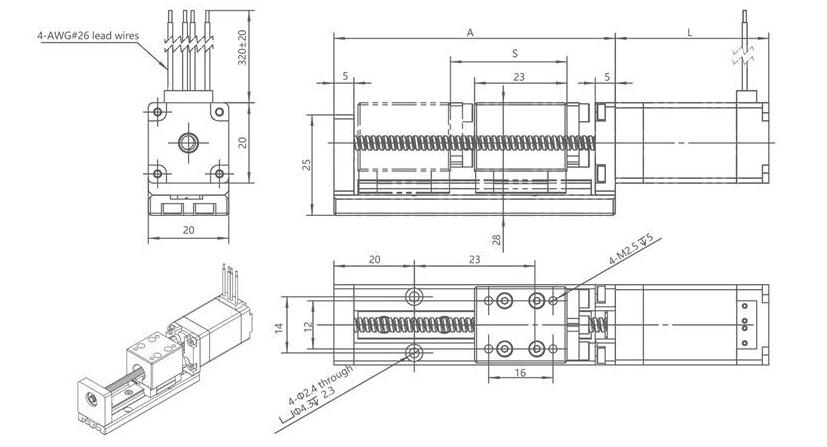
Stroke S (mm) | 30 | 60 | 90 | Size can |
Dimension A (mm) | 70 | 100 | 130 |
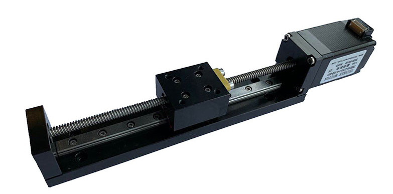
Customized NEMA8 Linear with origin switch outline drawing:
More Information on detail, please feel free to contact me

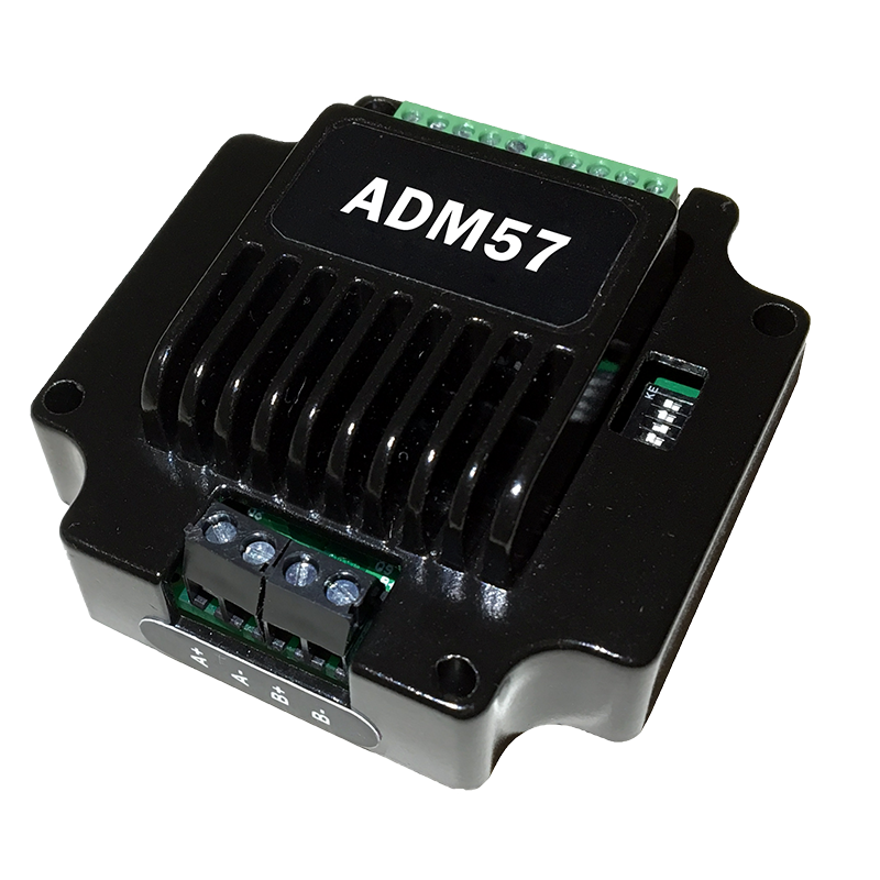
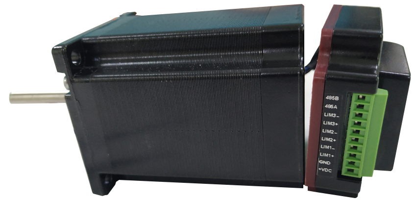
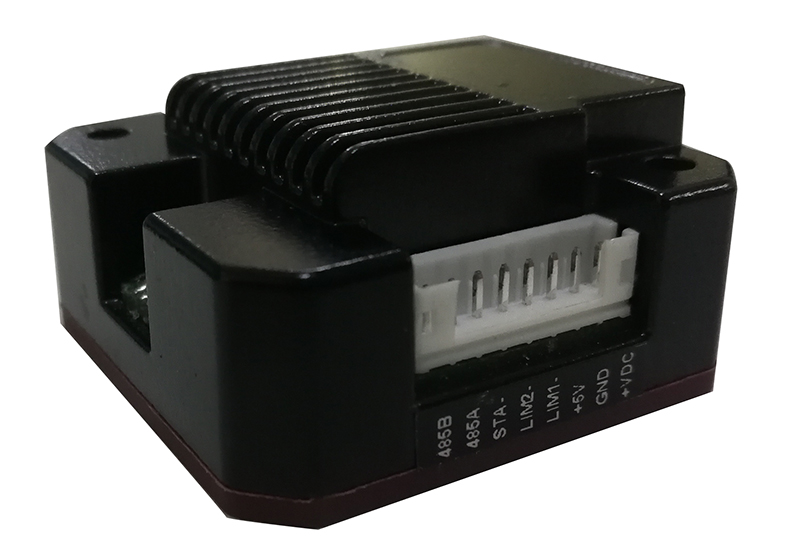
RS485 Serial Stepper Motor Controller, Design for NEMA23 Stepper Motors.
● Standard RS485 communication protocol and built-in motion control instructions.
● Multi-axes control, extending up to 32 axes for simultaneous control.
● DC input voltage 15~50VDC, recommended working voltage 36VDC.
● Continuous output current 4.0A max, max peak current 5.6A.
● Integrated design, mounted with NEMA23/NEMA34 stepper motor.
● Low vibration, low noise, stable operation, low motor heating.
● Any micro-step can be set .
● Protection functions such as overvoltage, undervoltage and overcurrent.
● Built-in automatic matching function of motor parameter.
● Serial port RS232/RS485 debugging function.
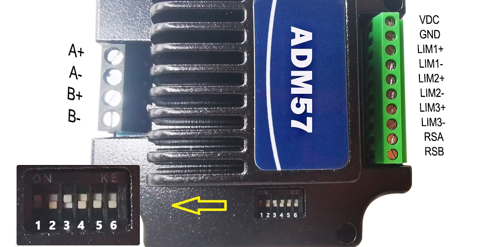
1.VDC: Positive power input: DC voltage 15-50VDC
2.GND: Negative power input: DC voltage GND
3.COM IO signal level common anode common terminal, amplitude 5VDC,
4.LIM1- Reverse limit signal port, valid for rising edge
5.LIM2- Reverse limit signal port, valid for rising edge
6.STA: Start and stop signal port, valid on rising edge
7.RSA: RS485 group A signal
8.RSB: RS485 group B signal
Working Principle:
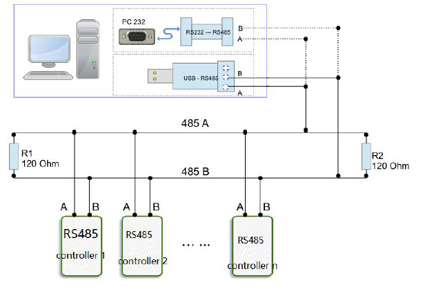
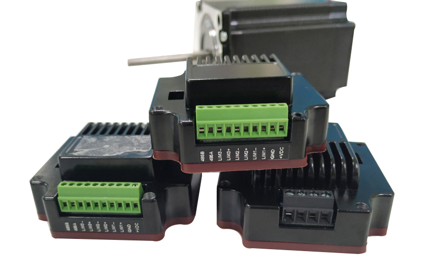
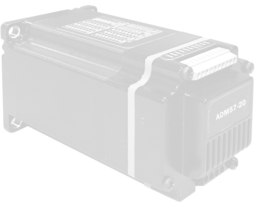
ADM57 stepper motor driver, using 6 DIP switch for set the communication baud rate and drive site:
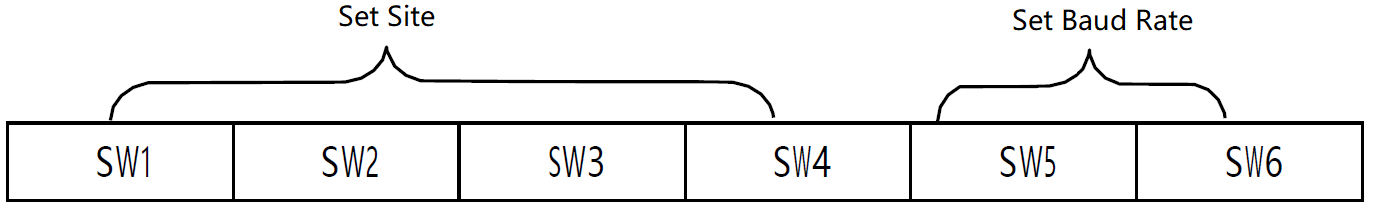
Device ID | SW1 | SW2 | SW3 | SW4 |
Broadcast | ON | ON | ON | ON |
1 | OFF | ON | ON | ON |
2 | ON | OFF | ON | ON |
3 | OFF | OFF | ON | ON |
4 | ON | ON | OFF | ON |
5 | OFF | ON | OFF | ON |
6 | ON | OFF | OFF | ON |
7 | OFF | OFF | OFF | ON |
8 | ON | ON | ON | OFF |
9 | OFF | ON | ON | OFF |
10 | ON | OFF | ON | OFF |
11 | OFF | OFF | ON | OFF |
12 | ON | ON | OFF | OFF |
13 | OFF | ON | OFF | OFF |
14 | ON | OFF | OFF | OFF |
15 | OFF | OFF | OFF | OFF |
Note: The formula for calculating the ID: ID=1*SW1 2*SW2 4*SW3 8*SW4.
The default ID value is 0. broadcast mode accept data but not return data.
Communication baud rate setting:
Baud Rate | SW5 | SW6 |
9600 | ON | ON |
19200 | OFF | ON |
38400 | ON | OFF |
57600 | OFF | OFF |
ADM57S Series RS485 Serial Stepper Motor Controller, NEMA23 Integrated Stepper Motor.
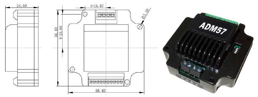
ADM57S RS485 Serial Stepper Motor Controller Manual 
More Information on detail, please feel free to contact me
CRC Check routine by C# :
Uint16 Funct_CRC16(unsigned char * puchMsg, Uint16 DataLen)
{
Uint16 i,j,tmp;
Uint16 crcdata=0xFFFF;
for(i=0;i<DataLen;i )
{
crcdata=(*puchMsg)^crcdata;
puchMsg ;
for(j=0;j<8;j )
{
tmp=crcdata&0x0001;
crcdata=crcdata>>1;
if(tmp){
crcdata=crcdata^0xA001;
}
}
}
returncrcdata;
}
Software Modbus Poll 
AdamPower Software

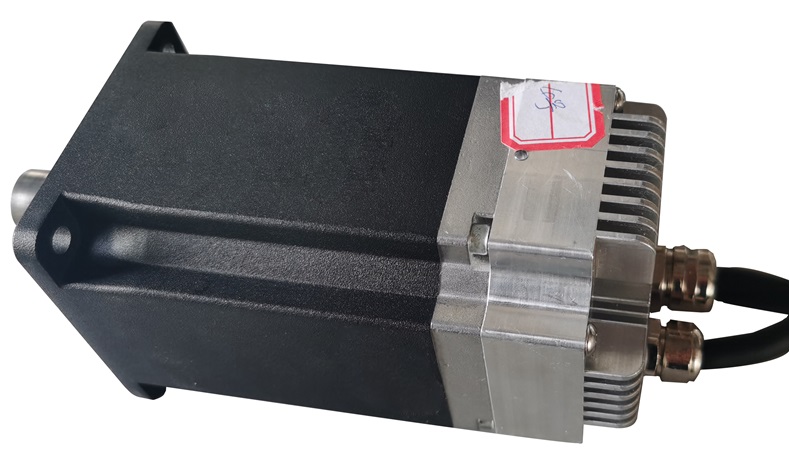
RS485 integrated servo motor, Low voltage servo Motor, NEMA24 size DC servo Motor.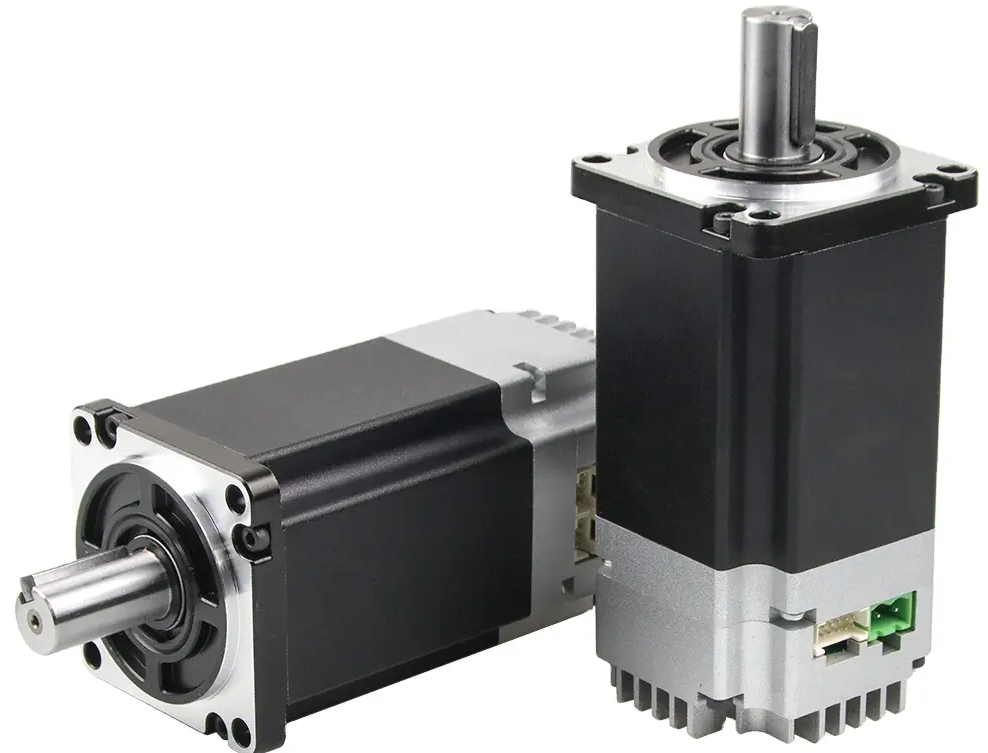
| Item | Specifications |
| Winding connection mode | Star connection |
| Encoder type | 17bit absolute encoder |
| Shaft Radial Play | 0.025mm |
| Radial clearance | 0.06mm@450g |
| Axial clearance | 0.08mm@450g |
| Maximum radial bearing force | 15N@20MM Start with the flange |
| Maximum radial axial force | 10N |
| Insulation grade | B Grade |
| Dielectric strength | 500VAC /minute |
| insulation resistance | Minimum 100Ω, 500VDC |
Motor Parameters
| Model Number | 60AIS95 | 60AIS113 |
| Rated voltage(V) | DC24V | DC48V |
| Rated power(W) | 200 | 400 |
| Rated current(A) | 12 | 11 |
| Rated torque(N. M) | 0.64 | 1.27 |
| Peak torque(N. M) | 1.27 | 3.82 |
| Rated speed(RPM) | 3000 ±10% | 3000 ±10% |
| Max speed(RPM) | 3200 ±10% | 3200 ±10% |
| Cable resistance(Ω) | 0.12 ±10% | 0.27 ±10% |
| Cable inductance(MH) | 0.36 ±10% | 0.56 ±10% |
| Torque coefficient(NM/A) | 0.06 ±10% | 0.12 ±10% |
| Length(MM) | 95 | 113 |
| Pole | 5 | |
| Level of protection | Ip54 | |
| Motor insulation class | Class F | |
Mechanical Dimensions and Wiring Diagram: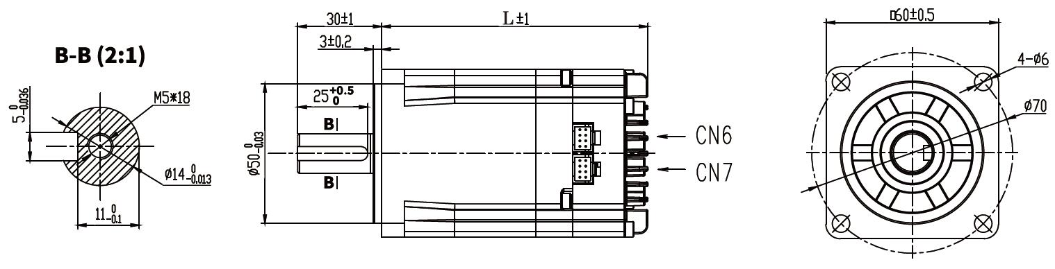
Port Definition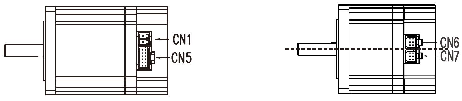
| Terminal | Name | Description | ||
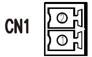 | 1 | DC | DC24-36V | |
| 2 | GND | Ground | ||
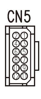 | 1 | D01 | Output Terminal 1 | Function depends on the user' setting |
| 2 | D01- | |||
| 3 | D02 | Output Terminal 2 | ||
| 4 | D02- | |||
| 8 | DI1 | Input Terminal 1 | ||
| 5 | DI2 | Input Terminal 2 | ||
| 6 | DI3 | Input Terminal 3 | ||
| 7 | DI_COM | The common terminal of the input terminal, Used to drive the input optocoupler, Connect DC12-24V (common positive NPN connection) or OV (common negative PNP connection) Current>100mA | ||
| 9 | DIR | Direction Control Signal Input | DC5-24V | |
| 10 | DIR- | |||
| 11 | PULS | Pulse Control Signal Input | ||
| 12 | PULS- | |||
| S/N | Name | Description | ||
CN6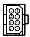 | 1 | 485A/T | RS485 | |
| 2 | NC | Reserved | ||
| 3 | 485B/T | RS485 - | ||
| 4 | NC | Reserved | ||
| 5 | GND | Ground | ||
| 6 | NC | Reserved | ||
| 7 | NC | Reserved | ||
| 8 | NC | Reserved | ||
| CN7 | 1 | 485A/T | RS485 | |
| 2 | NC | Reserved | ||
| 3 | 485B/T | RS485 - | ||
| 4 | NC | Reserved | ||
| 5 | GND | Ground | ||
| 6 | SWCLK/T | Program upgrade clock line | ||
| 7 | 3.3V | communication 3.3V power supply | ||
| 8 | SWDIO/T | Program upgrade data line | ||
| input power | The allowed input voltage of different models of AIMotor motor is not consistent. Please see the motor specifications for details Dc power input, pay attention to the positive and negative electrodes of the power supply | |
| operating environment | temperature | Working: 0℃ ~ 55℃ Storage: -20℃ ~ 80℃ |
| humidity | Less than 90% (no condensation) | |
| control method | ① position control ② speed control ③ torque control ④ communication control | |
| control characteristic | Speed frequency response: ≥200Hz | |
| Velocity fluctuation: < ±0.03 (load 0 ~ 100%) : < ±0.02×(0.9 ~ 1.1) supply voltage | ||
| Receiving pulse frequency ≤100kHz | ||
| control input | 01, servo enable; 02, alarm clearance; 03, multi-segment enable; 04, multi-segment select 1; 05, many paragraphs choose 2; 06, forward overrange; 07, reverse overrange; 08, positive turn point; 09, reverse point movement; 10. Origin switch 11, origin enable; 12. Emergency shutdown; 13. Pulse prohibition; 14. Remove position deviation; | |
| Control output | 01, the servo is ready to output; 02. Complete the output of positioning; 03, fault alarm output 04. Confirm the origin back to zero output; 05, electrical confirmation back to zero output; 06, torque to the output; 07, the speed reaches the output; | |
| position control | Pulse mode: pulse direction; A plus B orthogonal pulse The electronic gear ratio defaults to 131072:1000, that is, 1000 pulses per turn Maximum pulse receiving frequency <=100KHZ | |
| Internal 4 section position mode: 1. Single cycle operation; 2, automatic cycle operation; 3. Multi-segment DI switch operation | ||
| Communication control mode: RS485 Modbus_Rtu controls the corresponding communication location and address | ||
| speed control | Internal 4 speed mode: 1, single cycle operation; 2, automatic cycle operation; 3. Multi-speed DI switching operation | |
| Communication control mode: RS485 Modbus_Rtu controls the corresponding communication speed address | ||
| torque control | Communication control mode: RS485 Modbus_Rtu controls the corresponding communication torque address | |
| Acceleration and deceleration function | The time of ACC/DEC:1~65535 ms(0 r/min ~ 1000 r/min) | |
| Monitor function | Current speed, DI input, DO output, current position, command input pulse accumulation, average load rate, position deviation count, motor phase current, bus voltage value, module temperature, alarm record, command pulse frequency corresponding speed, running state, etc | |
| protect function | vervoltage and undervoltage of the main power supply, overspeed, overcurrent, overload, abnormal encoder, abnormal position, blocked rotation, abnormal parameters, etc | |
| Return to origin function | 13 autonomous (search) ways to return to the origin, as well as the origin offset function. | |
| RS485 function | It follows the standard ModBUS-RTU protocol One point two communication interface, convenient network parallel | |
| gain adjustment | Manually adjust Internal rigidity grade table adjustment | |
Connect to many slave stations via PLC device, with Simens S7-200Smart as an example: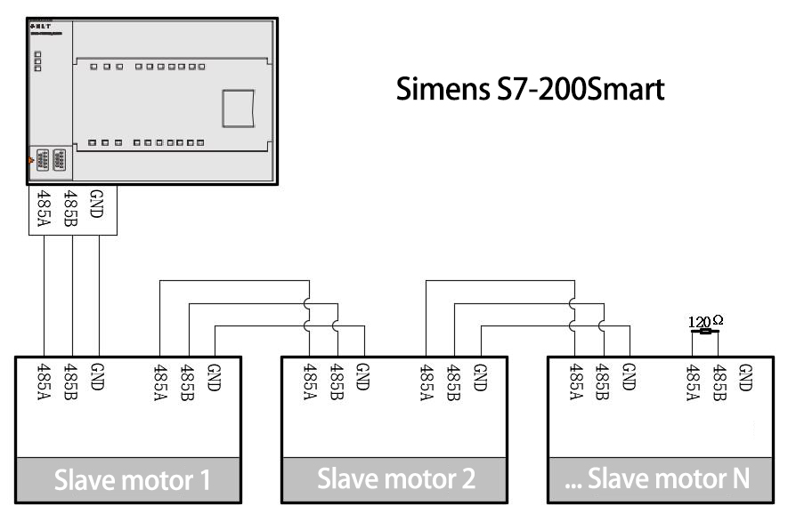
Host computer debugs a connection: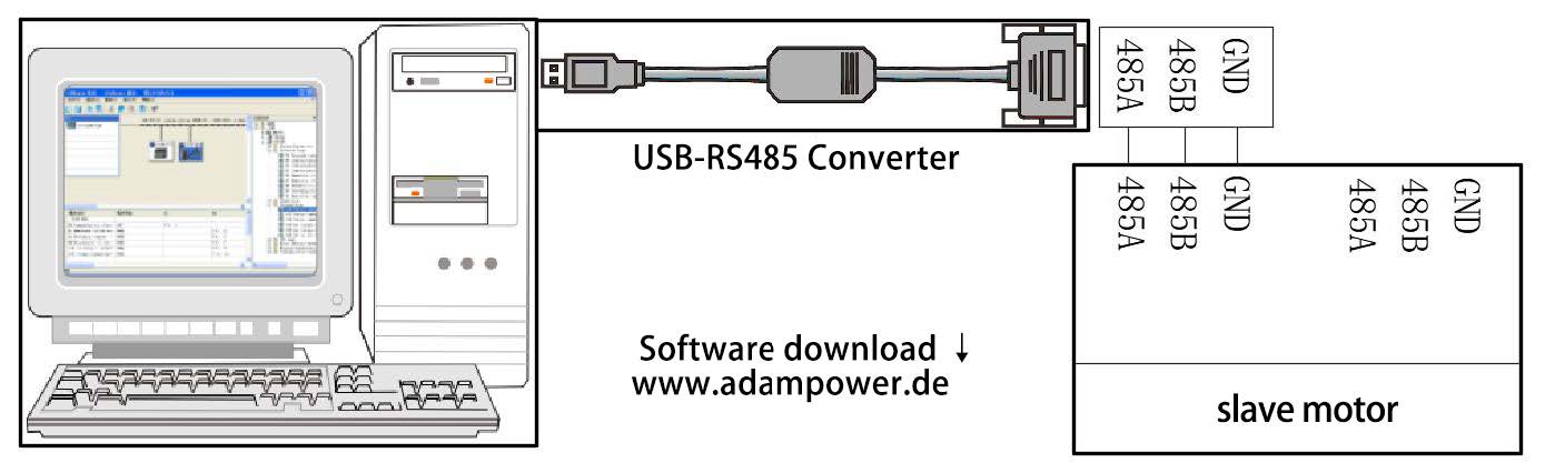
AIS series Integrated DC Servo Motor Software #ADMotor works well in PC, please download software
AIS Series RS485 Integrated Servo Motor User Manual
More Information on detail, please feel free to contact me

RS485 integrated servo motor, Low voltage servo Motor, NEMA23 size DC servo Motor.
Integrated Servo Motor, Low Voltage DC servo Motor With Cutomized Cable:
| Item | Specifications |
| Winding connection mode | Star connection |
| Encoder type | 17bit absolute encoder |
| Shaft Radial Play | 0.025mm |
| Radial clearance | 0.06mm@450g |
| Axial clearance | 0.08mm@450g |
| Maximum radial bearing force | 15N@20MM Start with the flange |
| Maximum radial axial force | 10N |
| Insulation grade | B Grade |
| Dielectric strength | 500VAC /minute |
| insulation resistance | Minimum 100Ω, 500VDC |
Motor Parameters
| Model Number | 57AIS61 | 57AIS77 | 57AIS100 |
| Rated voltage(V) | DC24V | DC24V | DC24V |
| Rated power(W) | 32 | 60 | 85 |
| Rated current(A) | 1.9 | 2.9 | 6.2 |
| Rated torque(N. M) | 0.48 | 0.63 | 1.45 |
| Peak torque(N. M) | 0.72 | 0.95 | 2.18 |
| Rated speed(RPM) | 1200 ±10% | 1000 ±10% | 1100 ±10% |
| Max speed(RPM) | 1800 ±10% | 1700 ±10% | 2100 ±10% |
| Cable resistance(Ω) | 2.73 ±10% | 1.52 ±10% | 0.73 ±10% |
| Cable inductance(MH) | 1.15 ±20% | 0.62 ±20% | 0.27 ±20% |
| Torque coefficient(NM/A) | 0.135 | 0.132 | 0.115 |
| Electrical time constant(MS) | 0.421 | 0.408 | 0.37 |
| Length(MM) | 61 | 77 | 100 |
| Pole | 14 | ||
| Level of protection | Ip65 | ||
| Motor insulation class | Class F | ||
Mechanical Dimensions and Wiring Diagram: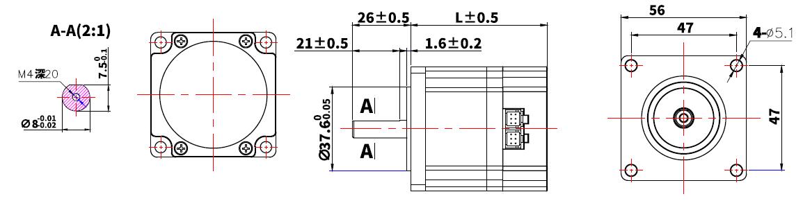
Port Definition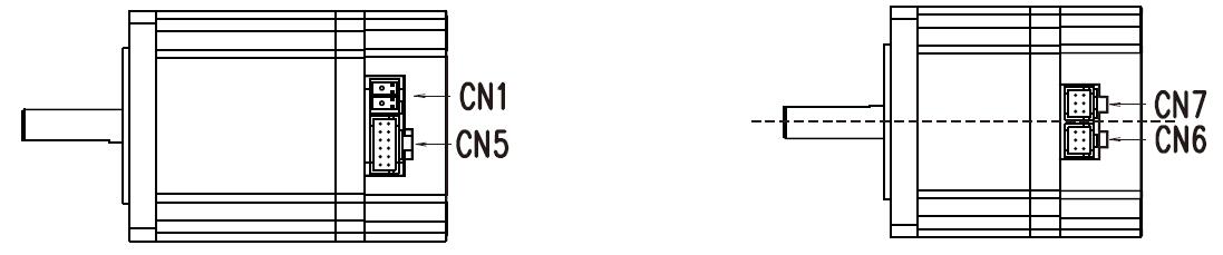
| Terminal | Name | Description | ||
| | 1 | DC | DC24-36V | |
| 2 | GND | Ground | ||
| | 1 | D01 | Output Terminal 1 | Function depends on the user' setting |
| 2 | D01- | |||
| 3 | D02 | Output Terminal 2 | ||
| 4 | D02- | |||
| 8 | DI1 | Input Terminal 1 | ||
| 5 | DI2 | Input Terminal 2 | ||
| 6 | DI3 | Input Terminal 3 | ||
| 7 | DI_COM | The common terminal of the input terminal, Used to drive the input optocoupler, Connect DC12-24V (common positive NPN connection) or OV (common negative PNP connection) Current>100mA | ||
| 9 | DIR | Direction Control Signal Input | DC5-24V | |
| 10 | DIR- | |||
| 11 | PULS | Pulse Control Signal Input | ||
| 12 | PULS- | |||
| Terminal | Name | Description | ||
CN6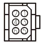 | 1 | 485A/T | RS485 | |
| 2 | NC | Reserved | ||
| 3 | 485B/T | RS485 - | ||
| 4 | NC | Reserved | ||
| 5 | GND | Ground | ||
| 6 | NC | Reserved | ||
| CN7 | 1 | 485A/T | RS485 | |
| 2 | SWCLK/T | Program upgrade clock line | ||
| 3 | 485B/T | RS485 - | ||
| 4 | SWDIO/T | Program upgrade data line | ||
| 5 | GND | Ground | ||
| 6 | 3.3V | communication 3.3V power supply | ||
| input power | The allowed input voltage of different models of AIMotor motor is not consistent. Please see the motor specifications for details Dc power input, pay attention to the positive and negative electrodes of the power supply | |
| operating environment | temperature | Working: 0℃ ~ 55℃ Storage: -20℃ ~ 80℃ |
| humidity | Less than 90% (no condensation) | |
| control method | ① position control ② speed control ③ torque control ④ communication control | |
| control characteristic | Speed frequency response: ≥200Hz | |
| Velocity fluctuation: < ±0.03 (load 0 ~ 100%) : < ±0.02×(0.9 ~ 1.1) supply voltage | ||
| Receiving pulse frequency ≤100kHz | ||
| control input | 01, servo enable; 02, alarm clearance; 03, multi-segment enable; 04, multi-segment select 1; 05, many paragraphs choose 2; 06, forward overrange; 07, reverse overrange; 08, positive turn point; 09, reverse point movement; 10. Origin switch 11, origin enable; 12. Emergency shutdown; 13. Pulse prohibition; 14. Remove position deviation; | |
| Control output | 01, the servo is ready to output; 02. Complete the output of positioning; 03, fault alarm output 04. Confirm the origin back to zero output; 05, electrical confirmation back to zero output; 06, torque to the output; 07, the speed reaches the output; | |
| position control | Pulse mode: pulse direction; A plus B orthogonal pulse The electronic gear ratio defaults to 131072:1000, that is, 1000 pulses per turn Maximum pulse receiving frequency <=100KHZ | |
| Internal 4 section position mode: 1. Single cycle operation; 2, automatic cycle operation; 3. Multi-segment DI switch operation | ||
| Communication control mode: RS485 Modbus_Rtu controls the corresponding communication location and address | ||
| speed control | Internal 4 speed mode: 1, single cycle operation; 2, automatic cycle operation; 3. Multi-speed DI switching operation | |
| Communication control mode: RS485 Modbus_Rtu controls the corresponding communication speed address | ||
| torque control | Communication control mode: RS485 Modbus_Rtu controls the corresponding communication torque address | |
| Acceleration and deceleration function | The time of ACC/DEC:1~65535 ms(0 r/min ~ 1000 r/min) | |
| Monitor function | Current speed, DI input, DO output, current position, command input pulse accumulation, average load rate, position deviation count, motor phase current, bus voltage value, module temperature, alarm record, command pulse frequency corresponding speed, running state, etc | |
| protect function | vervoltage and undervoltage of the main power supply, overspeed, overcurrent, overload, abnormal encoder, abnormal position, blocked rotation, abnormal parameters, etc | |
| Return to origin function | 13 autonomous (search) ways to return to the origin, as well as the origin offset function. | |
| RS485 function | It follows the standard ModBUS-RTU protocol One point two communication interface, convenient network parallel | |
| gain adjustment | Manually adjust Internal rigidity grade table adjustment | |
Connect to many slave stations via PLC device, with Simens S7-200Smart as an example:
Host computer debugs a connection:
AIS series Integrated DC Servo Motor Software #ADMotor works well in PC, please download software
AIS Series RS485 Integrated Servo Motor User Manual
More Information on detail, please feel free to contact me

RS485 integrated servo motor, Low voltage servo Motor, 750W DC servo Motor.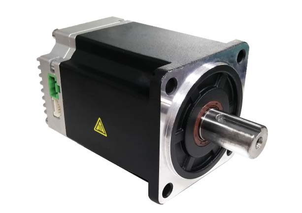
Integrated Servo Motor, DC Servo Motor with Customized Cable:
| Item | Specifications |
| Winding connection mode | Star connection |
| Encoder type | 17bit absolute encoder |
| Shaft Radial Play | 0.025mm |
| Radial clearance | 0.06mm@450g |
| Axial clearance | 0.08mm@450g |
| Maximum radial bearing force | 15N@20MM Start with the flange |
| Maximum radial axial force | 10N |
| Insulation grade | B Grade |
| Dielectric strength | 500VAC /minute |
| insulation resistance | Minimum 100Ω, 500VDC |
Motor Parameters
| Model Number | 80AIS112 |
| Rated voltage(V) | DC48V |
| Rated power(W) | 750 |
| Rated current(A) | 18 |
| Rated torque(N. M) | 2.4 |
| Peak torque(N. M) | 4.8 |
| Rated speed(RPM) | 3000 ±10% |
| Max speed(RPM) | 3200 ±10% |
| Cable resistance(Ω) | 0.08 ±10% |
| Cable inductance(MH) | 0.24 ±10% |
| Torque coefficient(NM/A) | 0.12 ±10% |
| Length(MM) | 112 |
| Pole | 5 |
| Level of protection | Ip65 |
| Motor insulation class | Class F |
Mechanical Dimensions and Wiring Diagram: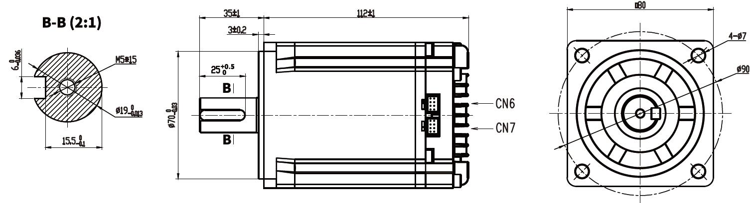
Port Definition
| Terminal | Name | Description | ||
| | 1 | DC | DC48V | |
| 2 | GND | Ground | ||
| | 1 | D01 | Output Terminal 1 | Function depends on the user' setting |
| 2 | D01- | |||
| 3 | D02 | Output Terminal 2 | ||
| 4 | D02- | |||
| 8 | DI1 | Input Terminal 1 | ||
| 5 | DI2 | Input Terminal 2 | ||
| 6 | DI3 | Input Terminal 3 | ||
| 7 | DI_COM | The common terminal of the input terminal, Used to drive the input optocoupler, Connect DC12-24V (common positive NPN connection) or OV (common negative PNP connection) Current>100mA | ||
| 9 | DIR | Direction Control Signal Input | DC5-24V | |
| 10 | DIR- | |||
| 11 | PULS | Pulse Control Signal Input | ||
| 12 | PULS- | |||
| S/N | Name | Description | ||
| CN6 | 1 | 485A/T | RS485 | |
| 2 | NC | Reserved | ||
| 3 | 485B/T | RS485 - | ||
| 4 | NC | Reserved | ||
| 5 | GND | Ground | ||
| 6 | NC | Reserved | ||
| 7 | NC | Reserved | ||
| 8 | NC | Reserved | ||
| CN7 | 1 | 485A/T | RS485 | |
| 2 | NC | Reserved | ||
| 3 | 485B/T | RS485 - | ||
| 4 | NC | Reserved | ||
| 5 | GND | Ground | ||
| 6 | SWCLK/T | Program upgrade clock line | ||
| 7 | 3.3V | communication 3.3V power supply | ||
| 8 | SWDIO/T | Program upgrade data line | ||
| input power | The allowed input voltage of different models of AIMotor motor is not consistent. Please see the motor specifications for details Dc power input, pay attention to the positive and negative electrodes of the power supply | |
| operating environment | temperature | Working: 0℃ ~ 55℃ Storage: -20℃ ~ 80℃ |
| humidity | Less than 90% (no condensation) | |
| control method | ① position control ② speed control ③ torque control ④ communication control | |
| control characteristic | Speed frequency response: ≥200Hz | |
| Velocity fluctuation: < ±0.03 (load 0 ~ 100%) : < ±0.02×(0.9 ~ 1.1) supply voltage | ||
| Receiving pulse frequency ≤100kHz | ||
| control input | 01, servo enable; 02, alarm clearance; 03, multi-segment enable; 04, multi-segment select 1; 05, many paragraphs choose 2; 06, forward overrange; 07, reverse overrange; 08, positive turn point; 09, reverse point movement; 10. Origin switch 11, origin enable; 12. Emergency shutdown; 13. Pulse prohibition; 14. Remove position deviation; | |
| Control output | 01, the servo is ready to output; 02. Complete the output of positioning; 03, fault alarm output 04. Confirm the origin back to zero output; 05, electrical confirmation back to zero output; 06, torque to the output; 07, the speed reaches the output; | |
| position control | Pulse mode: pulse direction; A plus B orthogonal pulse The electronic gear ratio defaults to 131072:1000, that is, 1000 pulses per turn Maximum pulse receiving frequency <=100KHZ | |
| Internal 4 section position mode: 1. Single cycle operation; 2, automatic cycle operation; 3. Multi-segment DI switch operation | ||
| Communication control mode: RS485 Modbus_Rtu controls the corresponding communication location and address | ||
| speed control | Internal 4 speed mode: 1, single cycle operation; 2, automatic cycle operation; 3. Multi-speed DI switching operation | |
| Communication control mode: RS485 Modbus_Rtu controls the corresponding communication speed address | ||
| torque control | Communication control mode: RS485 Modbus_Rtu controls the corresponding communication torque address | |
| Acceleration and deceleration function | The time of ACC/DEC:1~65535 ms(0 r/min ~ 1000 r/min) | |
| Monitor function | Current speed, DI input, DO output, current position, command input pulse accumulation, average load rate, position deviation count, motor phase current, bus voltage value, module temperature, alarm record, command pulse frequency corresponding speed, running state, etc | |
| protect function | vervoltage and undervoltage of the main power supply, overspeed, overcurrent, overload, abnormal encoder, abnormal position, blocked rotation, abnormal parameters, etc | |
| Return to origin function | 13 autonomous (search) ways to return to the origin, as well as the origin offset function. | |
| RS485 function | It follows the standard ModBUS-RTU protocol One point two communication interface, convenient network parallel | |
| gain adjustment | Manually adjust Internal rigidity grade table adjustment | |
Connect to many slave stations via PLC device, with Simens S7-200Smart as an example:
Host computer debugs a connection:
AIS series Integrated DC Servo Motor Software #ADMotor works well in PC, please download software
AIS Series RS485 Integrated Servo Motor User Manual
More Information on detail, please feel free to contact me

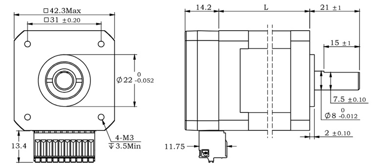
RS485 Serial Stepper Motor Controller, Design for NEMA17 Stepper Motors.
● Miniature size 42.3mmx42.3mm x21mm
● Standard RS485 communication protocol and built-in motion control instructions.
● Multi-axes control, extending up to 32 axes for simultaneous control.
● DC input voltage 12~32VDC, recommended working voltage 24VDC.
● Continuous output current 1.58A max, max peak current 2.2A.
● Integrated design, mounted with 42/39mm stepper motor.
● Low vibration, low noise, stable operation, low motor heating.
● Any micro-step can be set .
● Protection functions such as overvoltage, undervoltage and overcurrent.
● Built-in automatic matching function of motor parameter.
● Serial port RS232/RS485 debugging function.
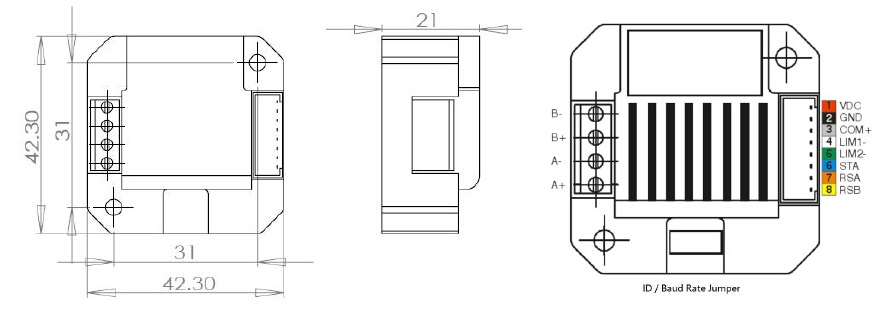
1.VDC: Positive power input: DC voltage 12-32VDC
2.GND: Negative power input: DC voltage GND
3.COM IO signal level common anode common terminal, amplitude 5VDC,
4.LIM1- Reverse limit signal port, valid for rising edge
5.LIM2- Reverse limit signal port, valid for rising edge
6.STA: Start and stop signal port, valid on rising edge
7.RSA: RS485 group A signal
8.RSB: RS485 group B signal
Working Principle:
ADM42 Series RS485 Stepper Motor Controller with NEMA17 size plastic flange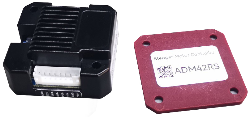
When the RS485 Stepper Motor Controller without this NEMA17 Plastic Flange,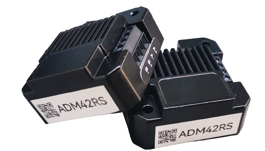
It can be assembled to NEMA17 Stepper Motor directly.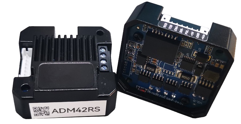
NEMA17 Integrated Stepper Motor, More concise and aesthetically pleasing.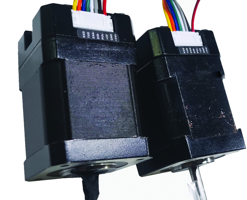
RS485 Stepper Motor Controller, using 6 DIP switch for set the communication baud rate and device ID.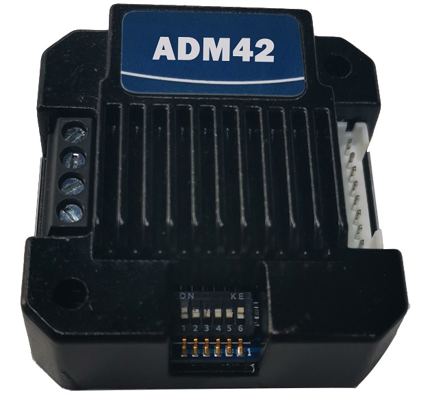
Device ID | SW1 | SW2 | SW3 | SW4 |
Broadcast | ON | ON | ON | ON |
1 | OFF | ON | ON | ON |
2 | ON | OFF | ON | ON |
3 | OFF | OFF | ON | ON |
4 | ON | ON | OFF | ON |
5 | OFF | ON | OFF | ON |
6 | ON | OFF | OFF | ON |
7 | OFF | OFF | OFF | ON |
8 | ON | ON | ON | OFF |
9 | OFF | ON | ON | OFF |
10 | ON | OFF | ON | OFF |
11 | OFF | OFF | ON | OFF |
12 | ON | ON | OFF | OFF |
13 | OFF | ON | OFF | OFF |
14 | ON | OFF | OFF | OFF |
15 | OFF | OFF | OFF | OFF |
Note: The formula for calculating the ID: ID=1*SW1 2*SW2 4*SW3 8*SW4.
The default ID value is 0. broadcast mode accept data but not return data.
Communication baud rate setting:
Baud Rate | SW5 | SW6 |
9600 | ON | ON |
19200 | OFF | ON |
38400 | ON | OFF |
57600 | OFF | OFF |
More Information on detail, please feel free to contact me
CRC Check routine by C# :
Uint16 Funct_CRC16(unsigned char * puchMsg, Uint16 DataLen)
{
Uint16 i,j,tmp;
Uint16 crcdata=0xFFFF;
for(i=0;i<DataLen;i )
{
crcdata=(*puchMsg)^crcdata;
puchMsg ;
for(j=0;j<8;j )
{
tmp=crcdata&0x0001;
crcdata=crcdata>>1;
if(tmp){
crcdata=crcdata^0xA001;
}
}
}
returncrcdata;
}
Software Modbus Poll
AdamPower Software

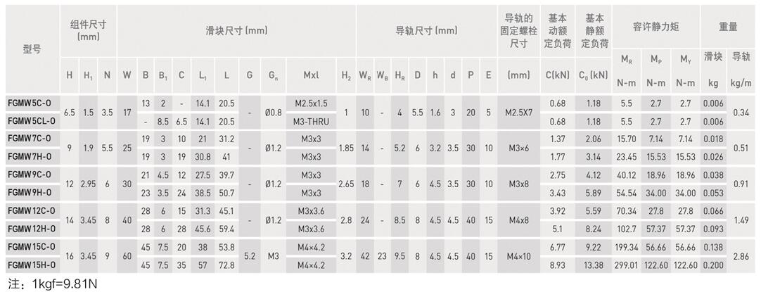
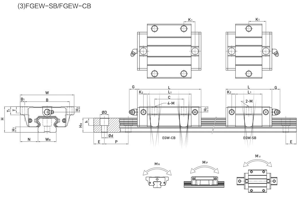
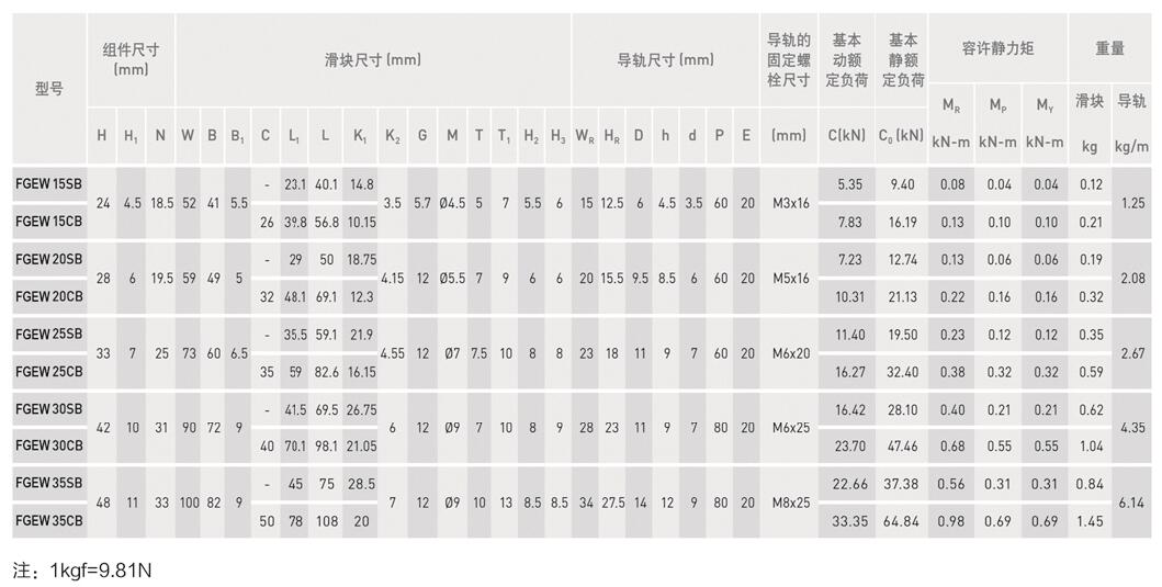
SPHERICAL GUIDE, Linear Guideway.
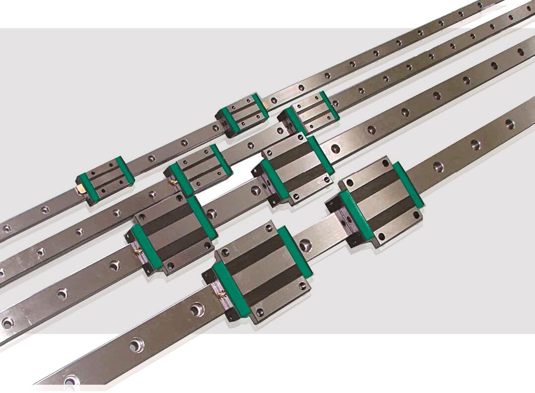
Linear Guideway, Heavy Load Ball Linear Guide, low assembly ball linear guide, and miniature ball linear guide:
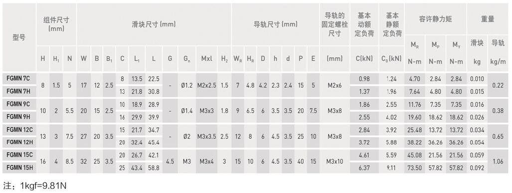
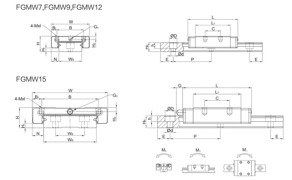
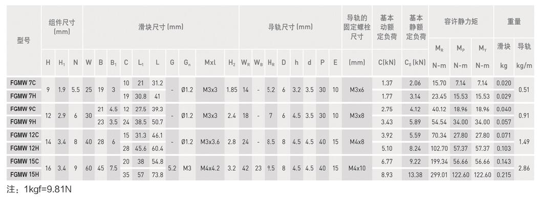
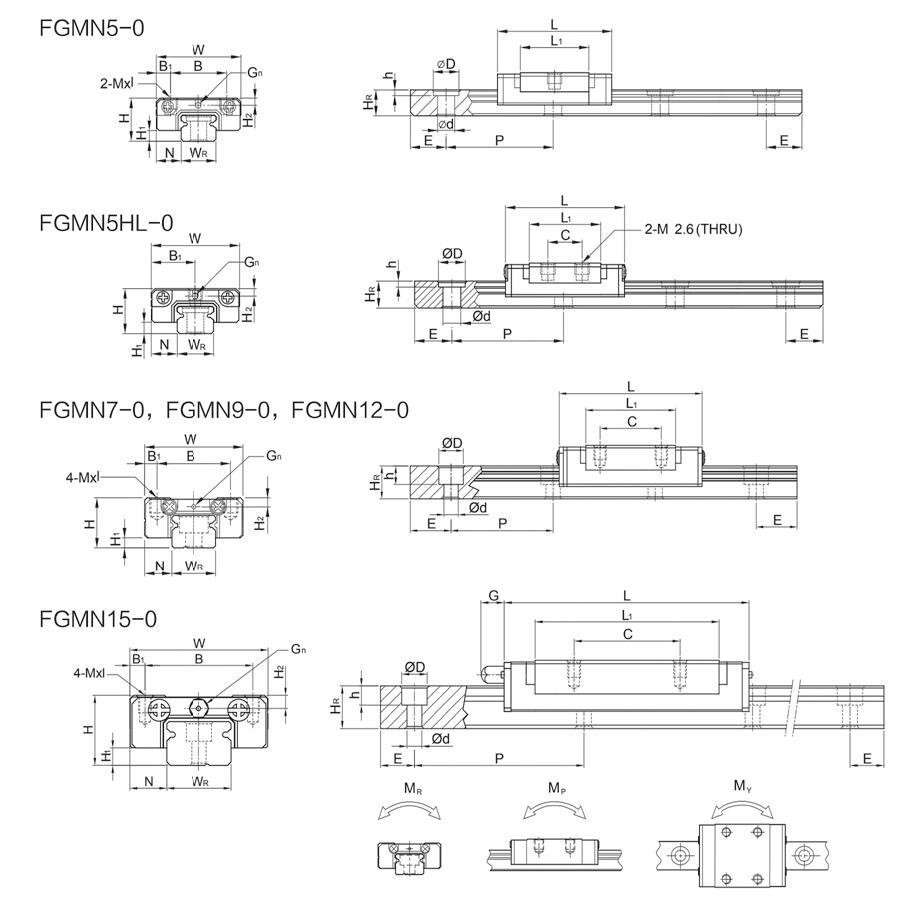
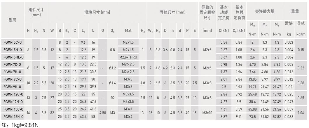
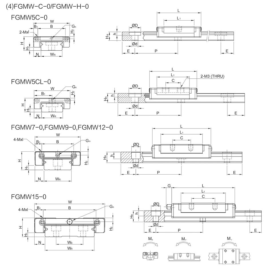
FGM series miniature ball linear guide: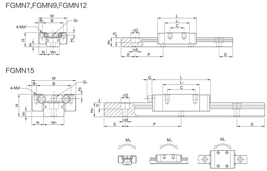
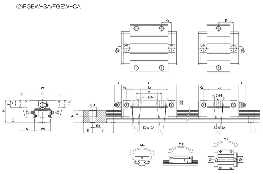
PGEH series low assembly ball linear guide: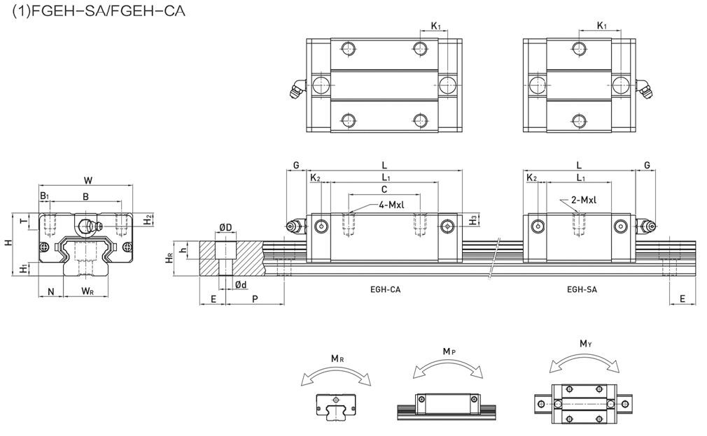
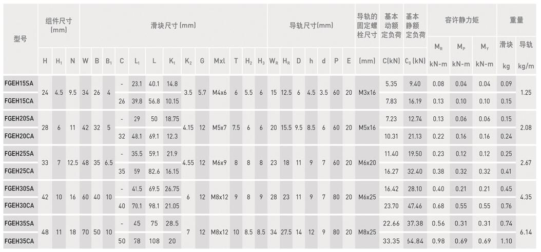
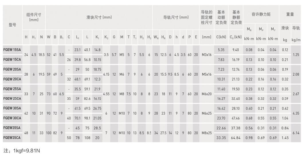
FGH series Heavy Load ball linear guide: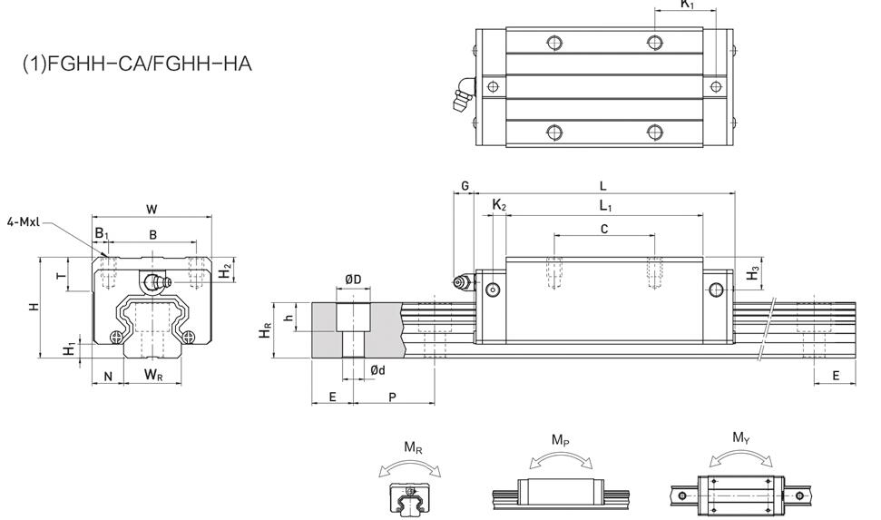
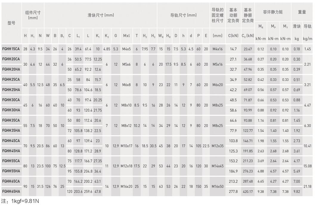
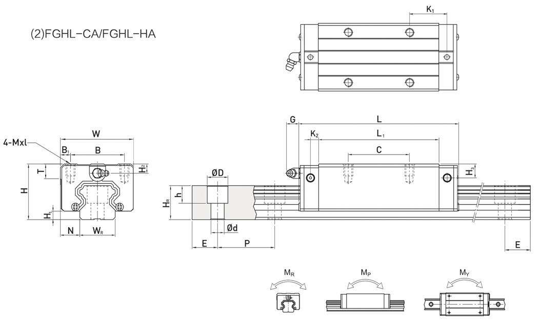
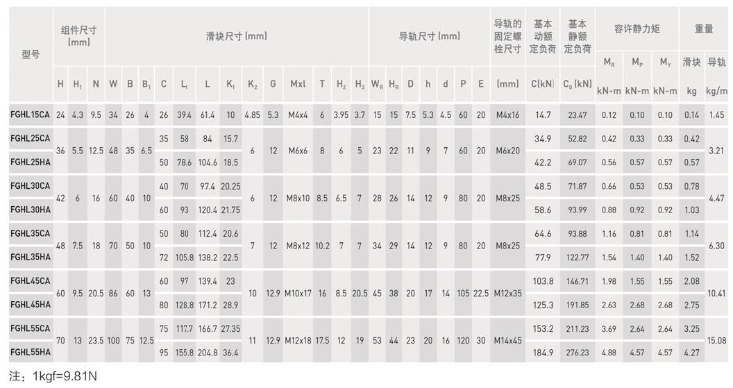
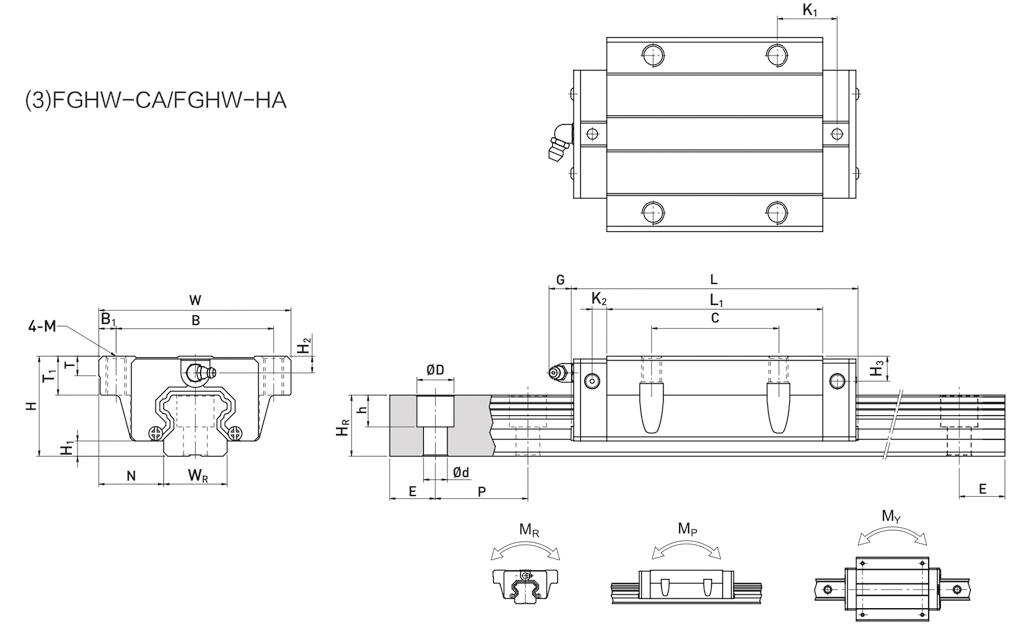
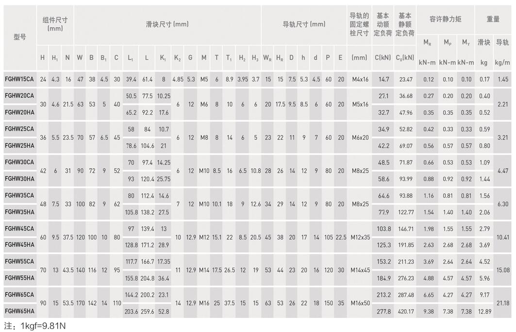
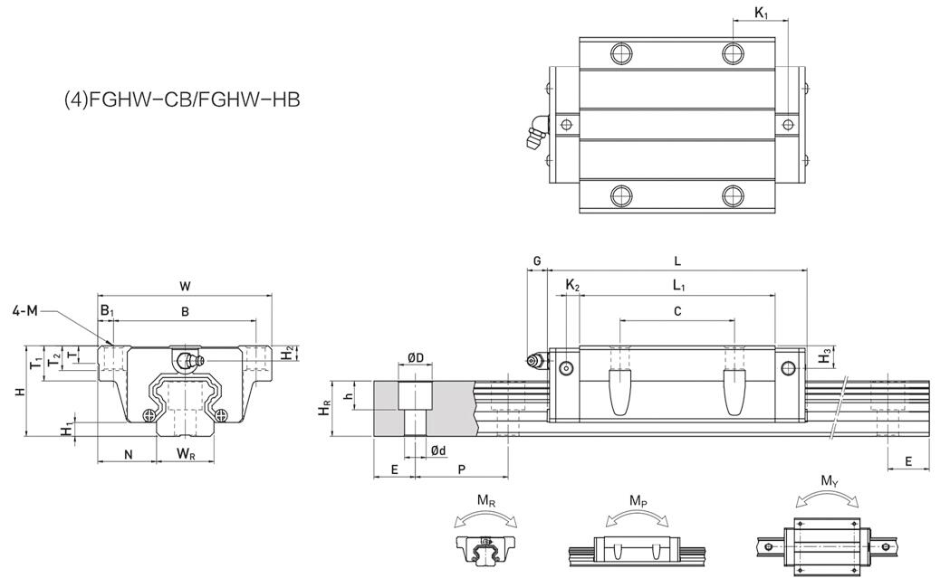
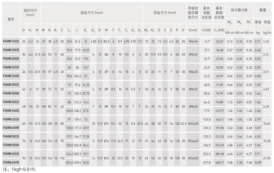
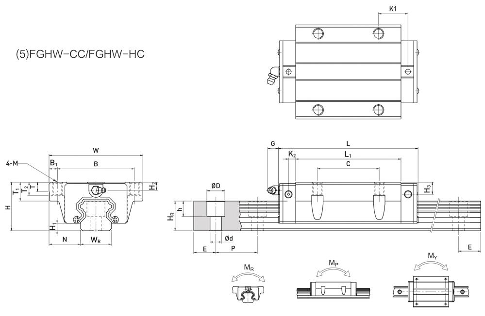
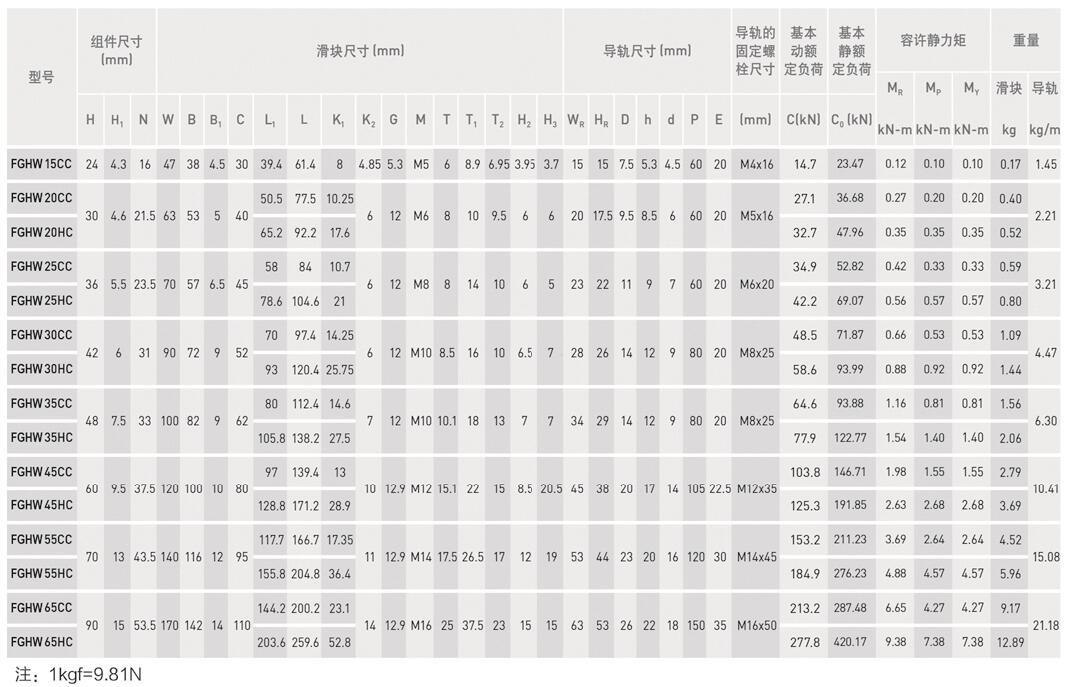
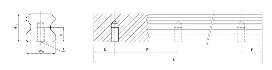
More Information on detail, please feel free to contact me

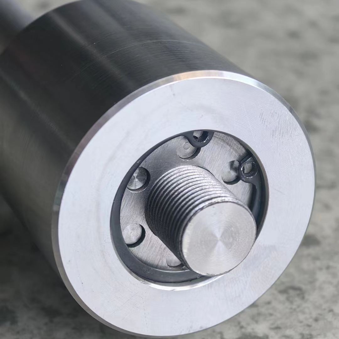
AdamPower is A high-tech enterprise specializing in the design and manufacturing of thread,
spline screw parts, and thread spline molds.has a strong scientific and technological strength
and is a university research base in the thread industry.
It has a key research project in Shanghai, including the Thread Research Cold Extrusion Tech-
nology Research Institute and Laboratory. Equipped with first-class equipment. provides
customers with design and manufacturing services for various standard and non-standard
threaded parts. has national invention patents in thread development research, multiple authoritative
awards, and important technical know-how.
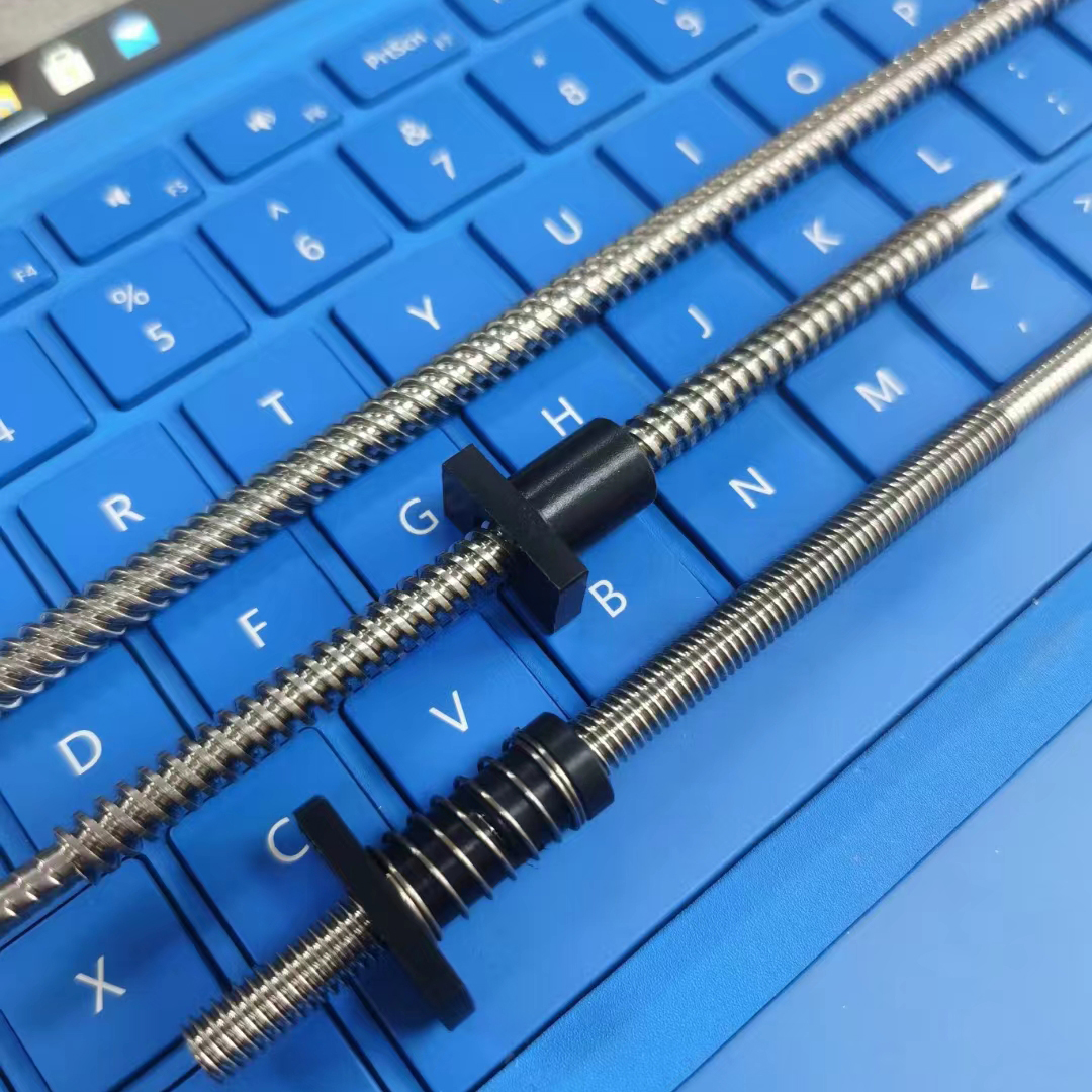
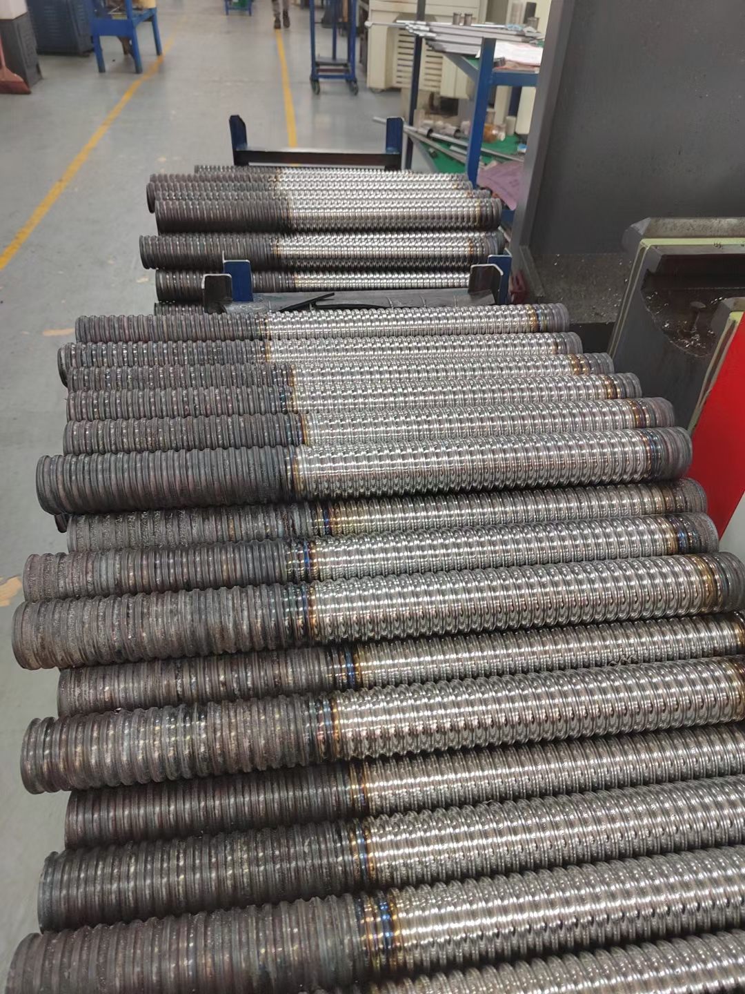
ACME US Standard Trapezoidal Thread -29°
Precision Screw Rod List:
| T3.5 | T3X0.5 | one-headed | T8 | T8x1 | one-headed |
| T3X1 P=0.5 | two-headed | T8x2 | one-headed | ||
| T3.5 | T3.5x0.6096 | one-headed | T8x4 P=2 | two-headed | |
| T3.5x1.2192 P=0.6096 | two-headed | T8x8 P=2 | four-headed | ||
| T3.5x2.43 P=1.2192 | two-headed | T8x12 P=3 | four-headed | ||
| T3.5x2.43 P=0.6096 | four-headed | T9.52 | T9.525x0.635 | one-headed | |
| T4.76 | T4.76x0.635 | one-headed | T9.525x1.2192 | one-headed | |
| T4.76x1.27 P=0.635 | two-headed | T9.525x2.43 P1.2192 | two-headed | ||
| T4.76X1.27 | one-headed | T9.525x2.54 | one-headed | ||
| T4.76x2.54P=1.27 | two-headed | T9.525x4.233P=2.116 | two-headed | ||
| T4.76x5.08 P=1.27 | four-headed | T9.525x5.08 P=2.54 | two-headed | ||
| T5 | T5X2 P=1 | two-headed | T9.525x10.16P=2.54 | four-headed | |
| T5.56 | T5.56X0.6096 | one-headed | T9.525x1.5875 | one-headed | |
| T5.56x1.2192 P=0.6096 | two-headed | T9.525x3.175 | one-headed | ||
| T5.56X1.2192 | one-headed | T9.525x3.175 P=1.5875 | two-headed | ||
| T5.56x1.5875 | one-headed | T9.525X6.35P=1.5875 | four-headed | ||
| T5.56X3.175 P=1.5875 | two-headed | T9.525x12.7P=1.5875 | eight-headed | ||
| T5.56x2.43P=1.2192 | two-headed | T9.86 | T9.86x19.05P=3.175 | six-headed | |
| T5.56x2.43 P=0.6096 | four-headed | T10 | T10x1 | one-headed | |
| T5.56X4.87P=1.2192 | four-headed | T10x2 | one-headed | ||
| T6.35 | T6.35x0.635 | one-headed | T10X2 P=1 | two-headed | |
| T6.35X1.27 P=0.635 | two-headed | T10X5 P=1 | four-headed | ||
| T6.35x1.27 | one-headed | T10×6 P=1 | six-headed | ||
| T6.35X1.5875 | one-headed | T10x4 P=2 | two-headed | ||
| T6.35X3.175 P=1.5875 | two-headed | T10x8 P=2 | four-headed | ||
| T6.35x2.43 | one-headed | T19.05 | T19.05x2.54 | one-headed | |
| T6.35x2.43P=1.2192 | two-headed | T12-T25.4 | Customized, one-headed to sixteen headed | ||
| T6.35x5.08 P=1.27 | four-headed | ||||
| T6.35x6.35 P=1.5875 | four-headed | ||||
| T6.35x12.7P=1.5875 | eight-headed | ||||
Metric trapezoidal thread -30°, Precision Screw Rod List:
| T3 | T3x0.5 | one-headed | T8 | T8x1 | one-headed |
| T3X1 P=0.5 | two-headed | T8x2 | one-headed | ||
| T3.5 | T3.5x0.5 | one-headed | T8x4 P=2 | two-headed | |
| T3.5x2 P=1 | two-headed | T8x8 P=2 | four-headed | ||
| T4 | T4x0.5 | one-headed | T9 | T9x1 | one-headed |
| T4x0.75 | one-headed | T9x2 P=1 | two-headed | ||
| T4X1 | one-headed | T9x2 | one-headed | ||
| T4X2 P=1 | two-headed | T9x4 P=2 | two-headed | ||
| T4X4 P=1 | four-headed | T9x5 P=2.5 | two-headed | ||
| T5 | T5x1 | one-headed | T9x10 P=2.5 | four-headed | |
| T5X2 P=1 | two-headed | T9.x1.5 | one-headed | ||
| T5X3 P=1 | three-headed | T9x3 P=1.5 | one-headed | ||
| T5x4 P=1 | four-headed | T9x3 P=1.5 | two-headed | ||
| T5x2 | one-headed | T9x6 P=1.5 | four-headed | ||
| T5x4 P=2 | two-headed | T9x12 P=1.5 | eight-headed | ||
| T5x1.25 | one-headed | T10 | T10x1 | one-headed | |
| T5x1.75 | one-headed | T10x1.5 | one-headed | ||
| T6 | T6X0.8 | one-headed | T10x2 P=1 | two-headed | |
| T6X1.6 P=0.8 | two-headed | T10x5 P=1 | five-headed | ||
| T6X3.2 P=0.8 | four-headed | T10x6 P=1 | six-headed | ||
| T6x1 | one-headed | T10x4 P=2 | two-headed | ||
| T6x2P=1 | two-headed | T10x8 P=2 | four-headed | ||
| T6x3 | one-headed | T10x9 P=1.5 | six-headed | ||
| T6x3 P=1 | two-headed | T12-T25 | Diaemter , Lead Screw Customized | one-headed to sixteen headed can be customized | |
| T6X4 P=2 | two-headed | ||||
| T6X6P=1 | six-headed | ||||
| T6X12 P=1.5 | eight-headed |
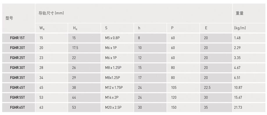
Mini Screw, tiny Screw even Fingertip screw can be customized as requirement.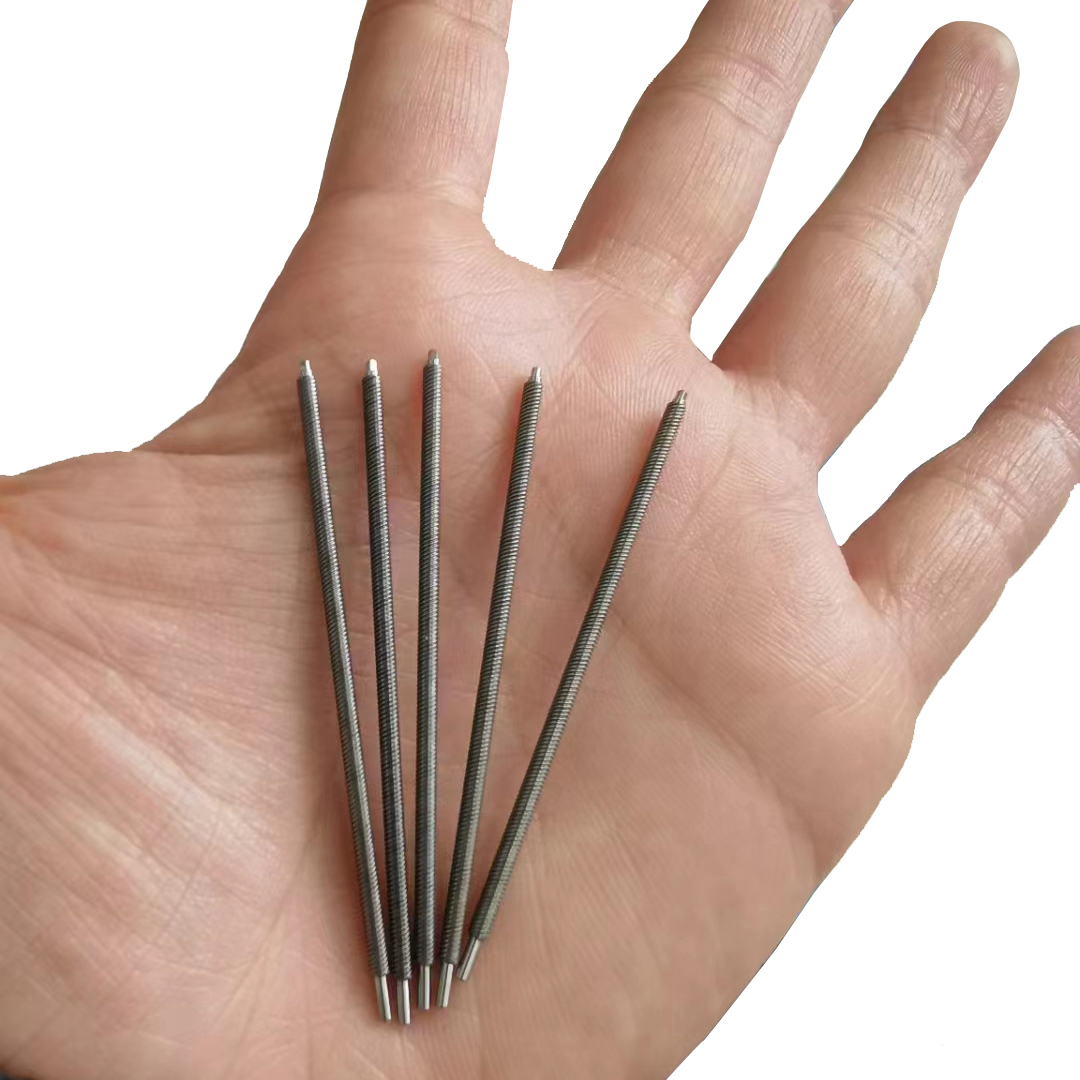
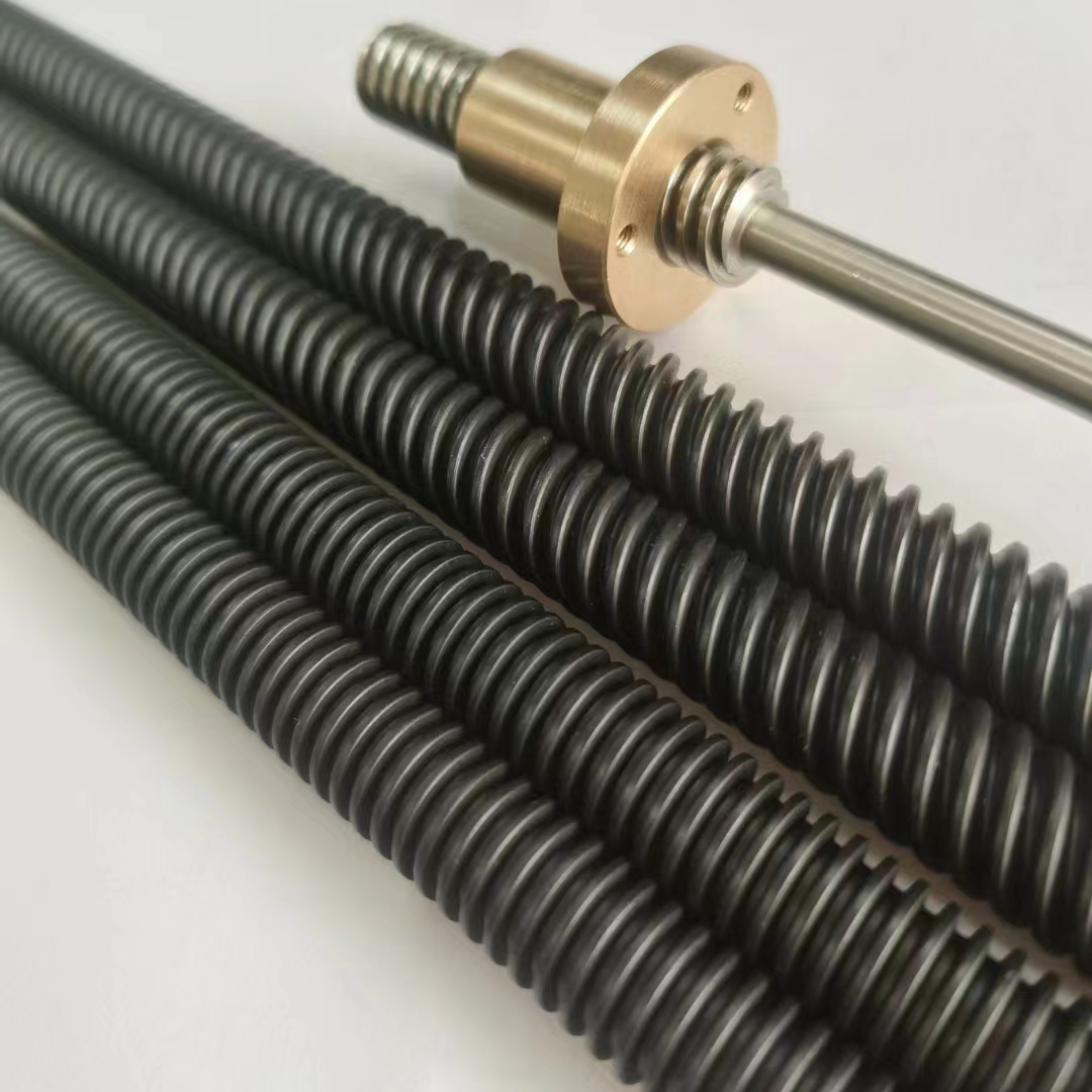
Planetary Screws:
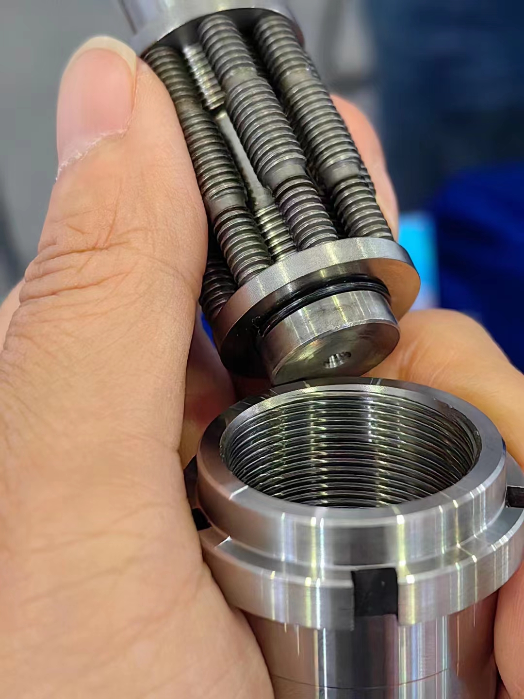
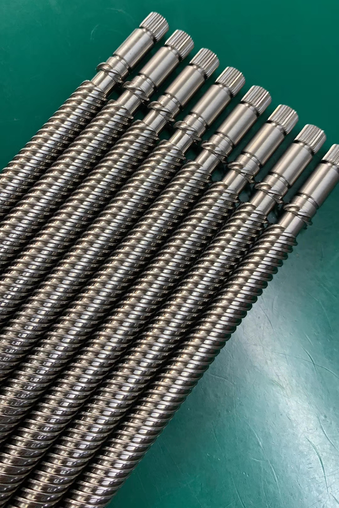
Customized Big Size Screw, Long Lead Travel, Bigger Diameters and so on.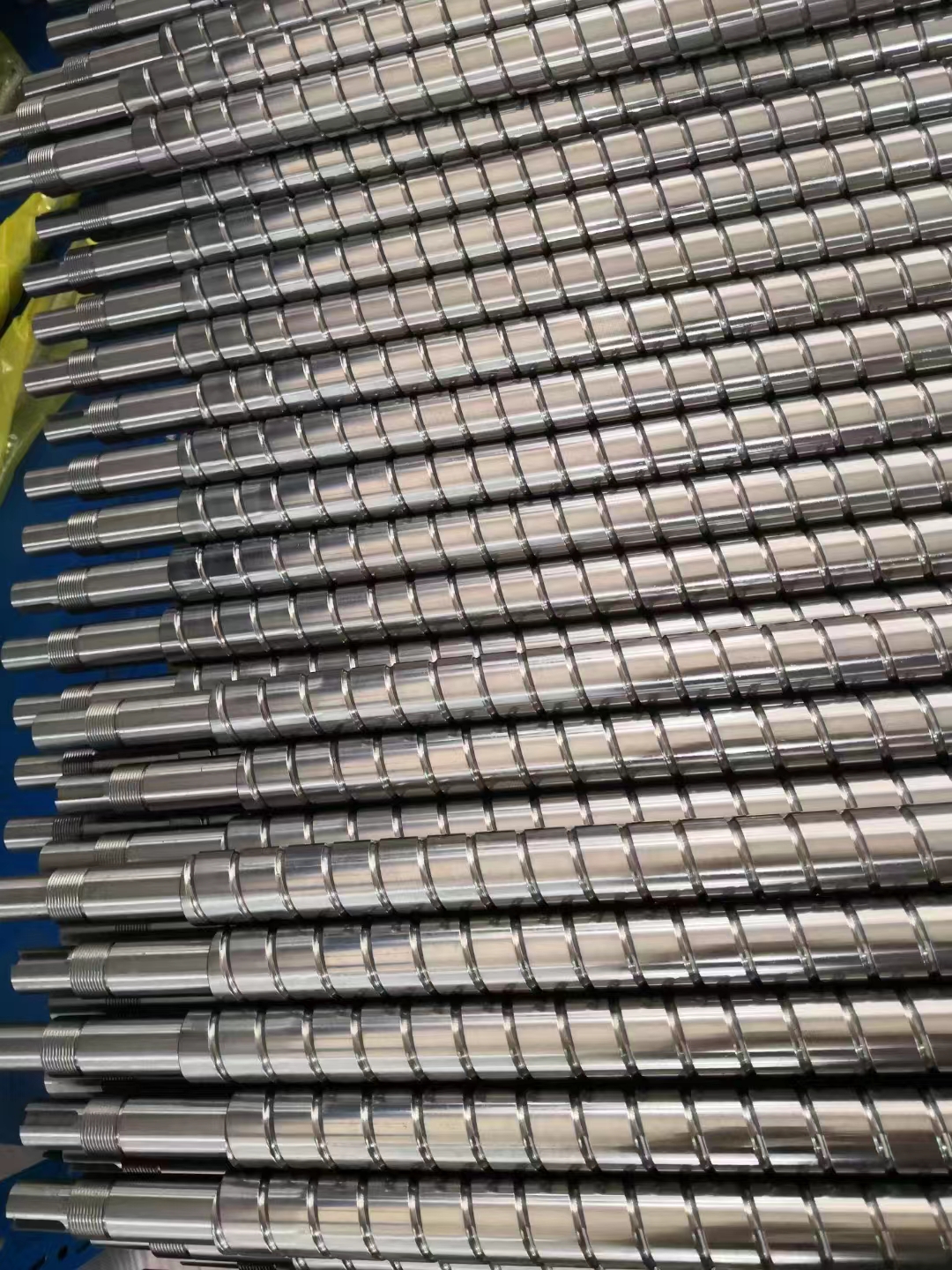
More Information on detail, please feel free to contact me

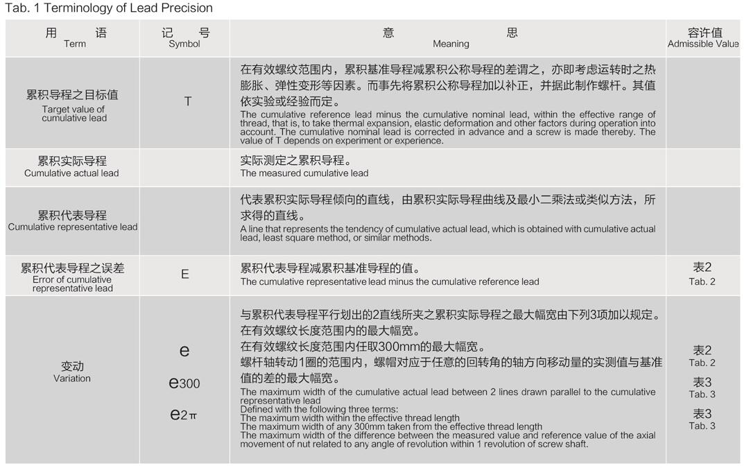
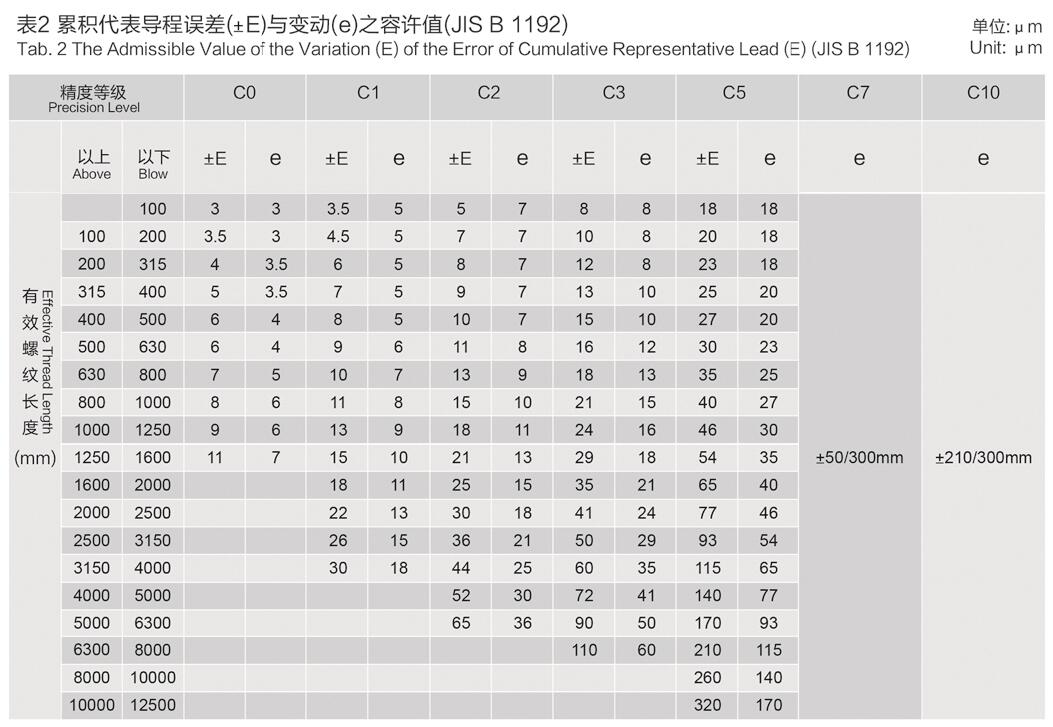
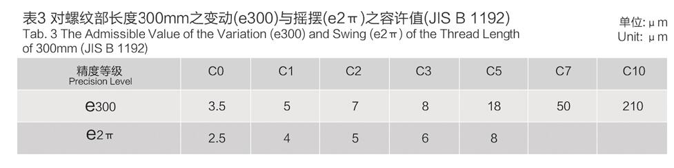
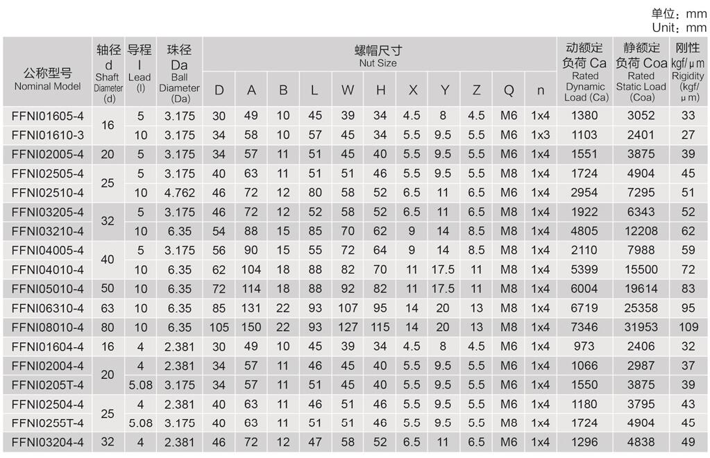
The lead precision of AdamPower precision ball screws (C3-C5) is based on JlS specifications
and specified with four features (Ee. e300 and e2r). The definition and admissible value of
each feature are shown in Fig. 1 and Tabs. 1-3. Generaly speaking, thecumulative lead errors
of bal screws C7 and C10 are used. the admissible value of the error of any 300mm taken
from the efectiveength of screw and e300 in Tab. 3. which are 0.05mm and 0.21mm respectively.
are used to definite the precision.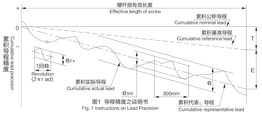
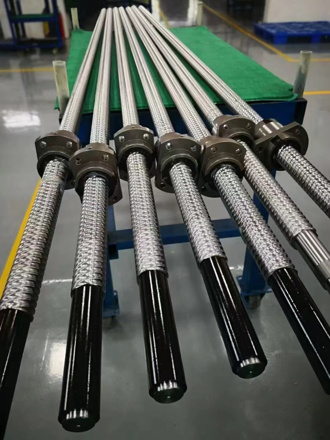
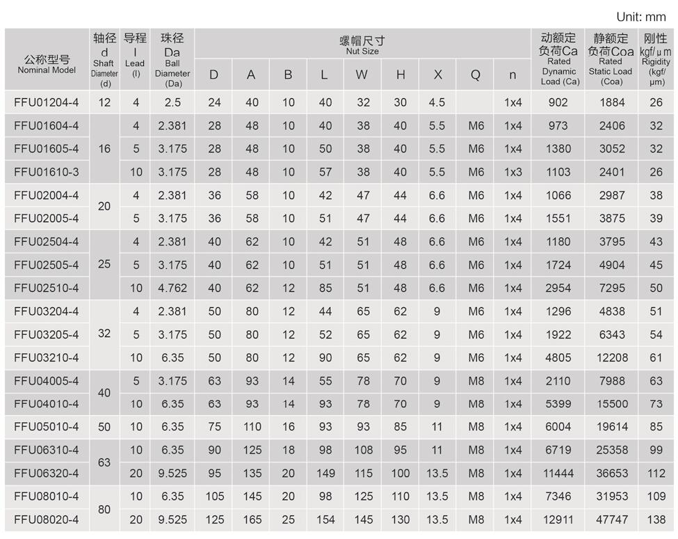
Ball Screw can be customized for special application requirement, ball thread length, full length of the screw, thread
direction: Right-handed or left-handed, and different nut structure(I, U, A, Y, S, K), and so on.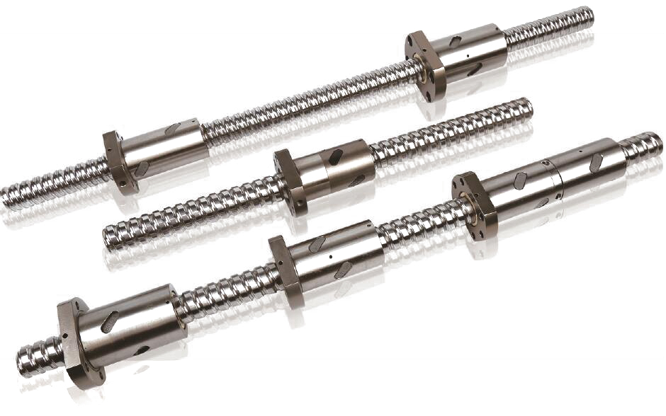
Numbering Rule of the Ball Screw: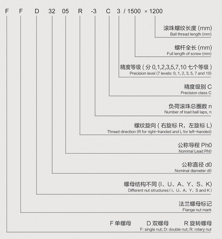
FFNU series Ball Screw:
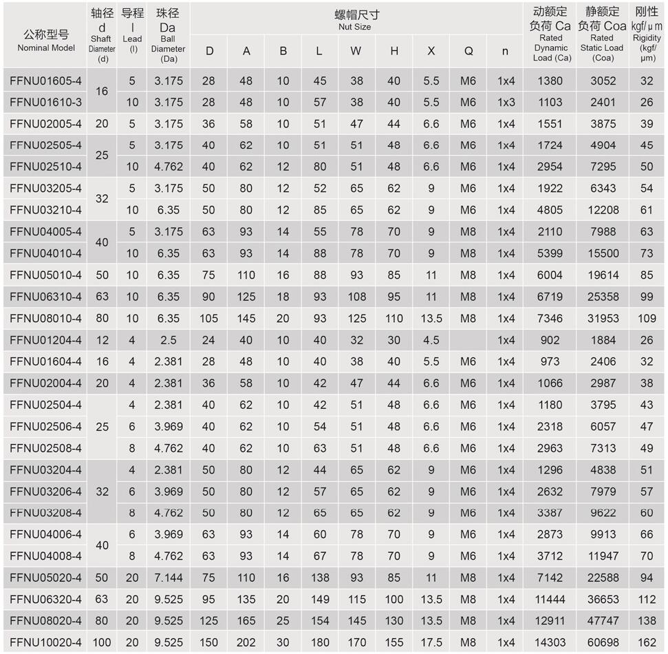
FFNI series Ball Screw: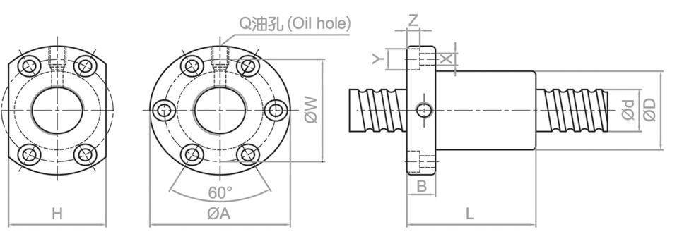
FFA series Ball Screw: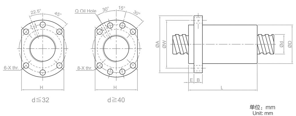
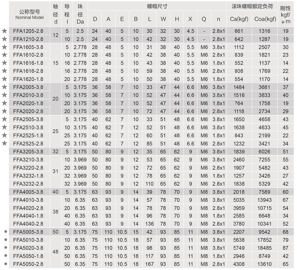
FFU series Ball Screw: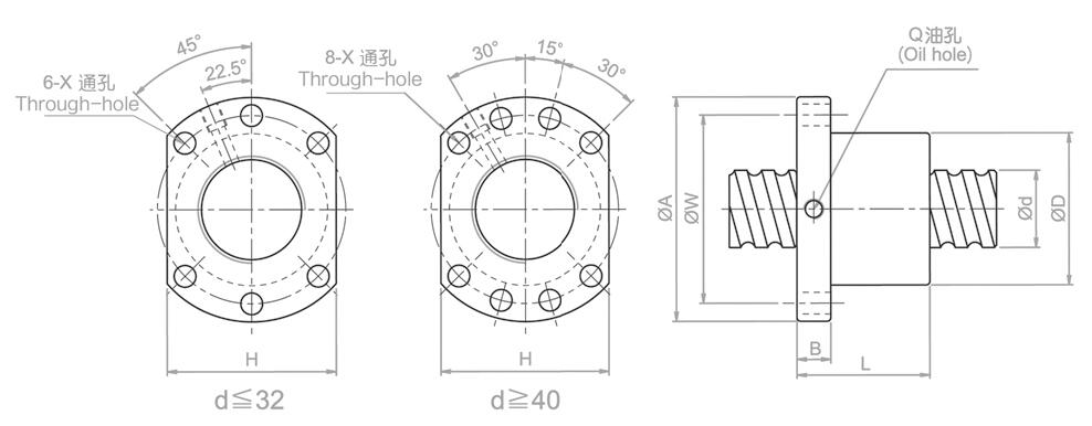
FFK series Ball Screw: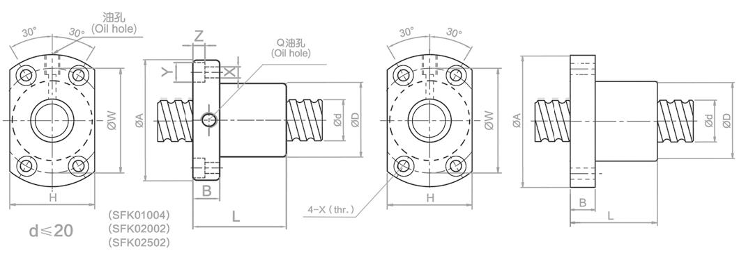
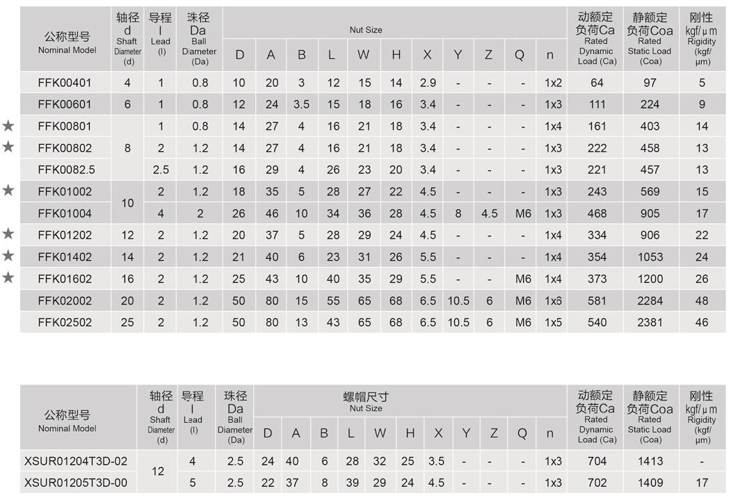
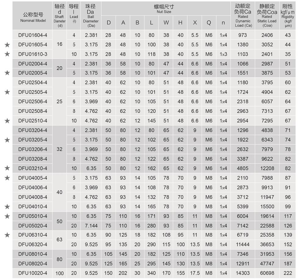
DFU series Ball Screw: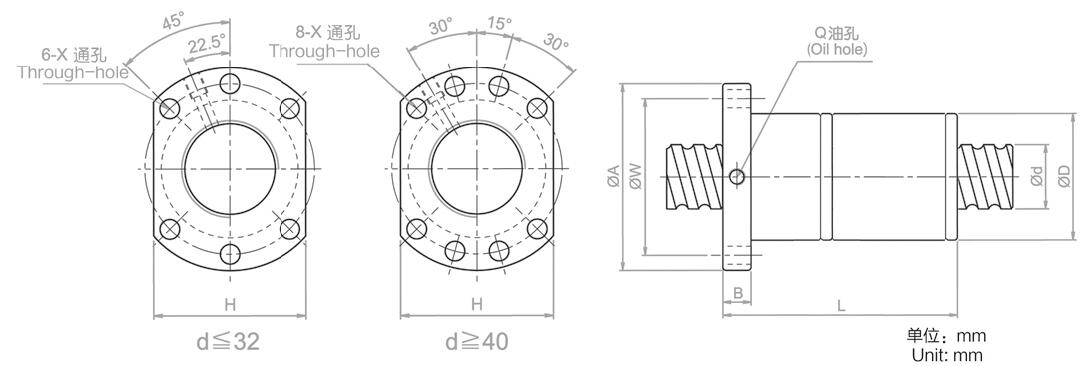
DFA series Ball Screw: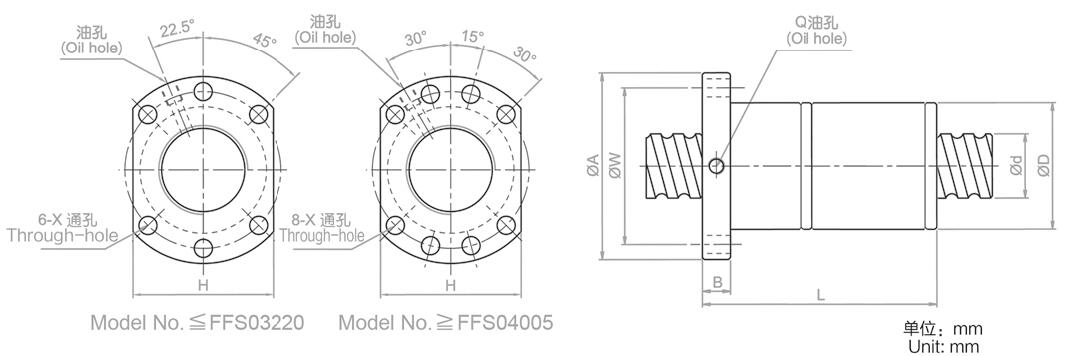
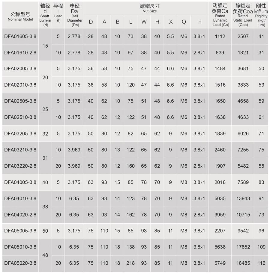
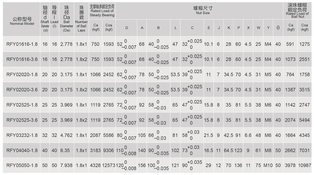
FFY series Ball Screw: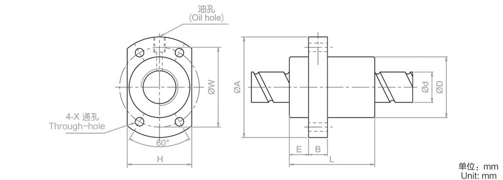
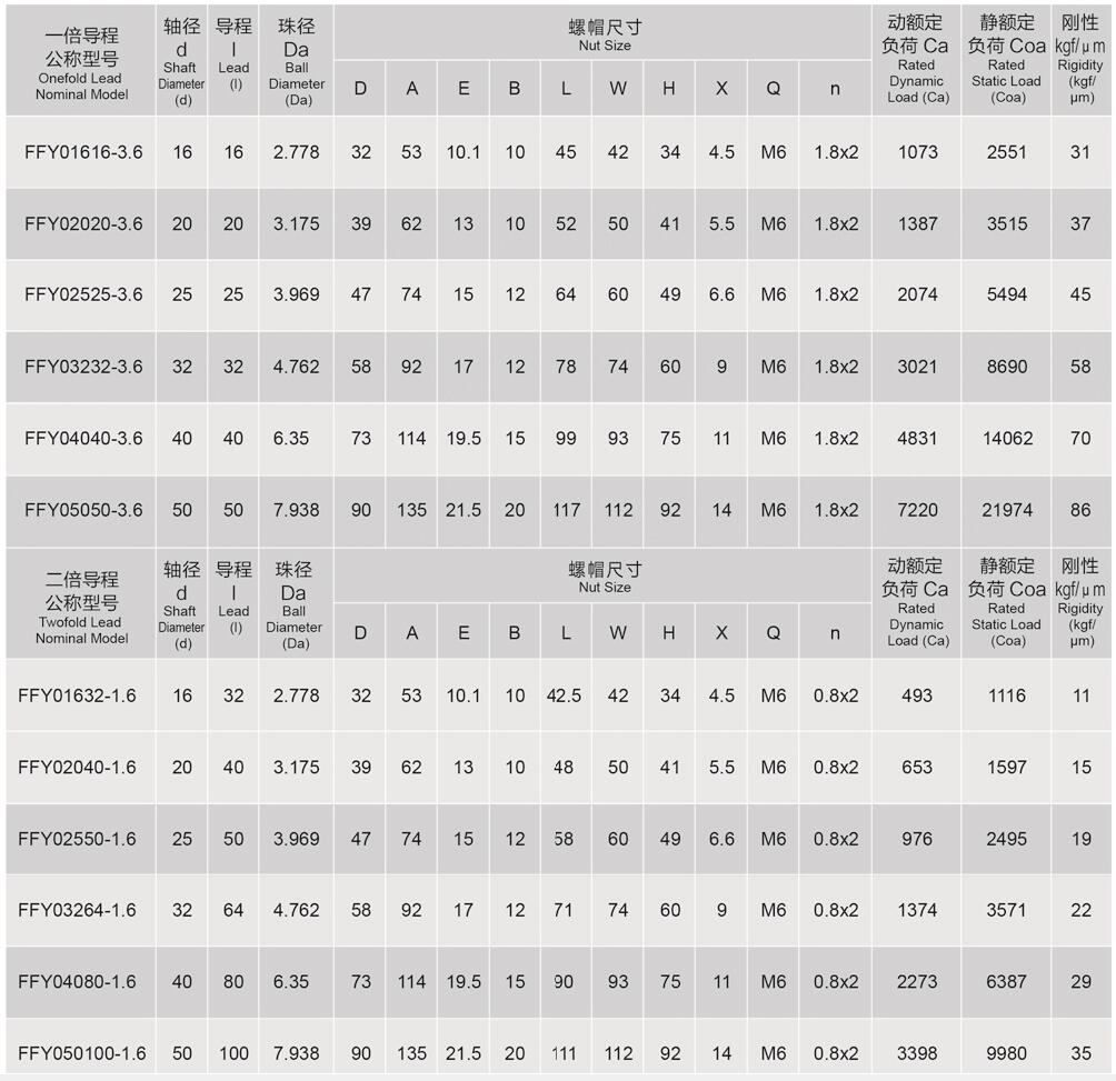
RFY series Ball Screw: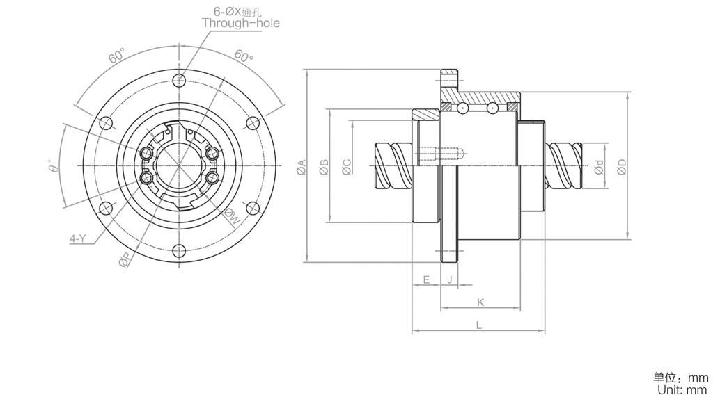
More Information on detail, please feel free to contact me

Pulse & direction stepper motor driver, support to Spontaneous pulses.
Spontaneous pulses Stepper Motor Driver with fixed working speed range.
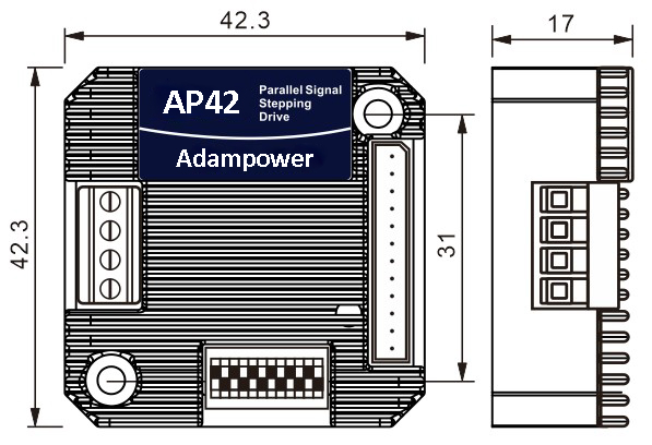
● Miniature size 42.3mmx42.3mm x17mm
● Pulse & direction stepper driver also support the standard RS232 serial command, and built-in 32bit digital chip.
● Using new control algorithms such for vibration suppression and low heat generation
● DC input voltage 12~40VDC, recommended working voltage 24VDC.
● Continuous output current 1.4A max, max peak current 2.2A.
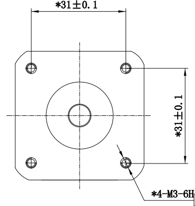
● Integrated design, mounted with NEMA17/NEMA16 stepper motor.
● Low vibration, low noise, stable operation, low motor heating.
● Any micro-step can be set .
● Protection functions such as overvoltage, undervoltage and overcurrent.
● Built-in automatic matching function of motor parameter.
● AP42 stepper driver can be assembled for NEMA17 Integrated Stepper Motors
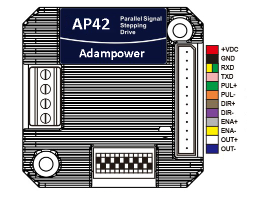
| Pin No. | Name | Description |
| 1 | VDC | Supply voltage: 12-32VDC, Recommend DC24V |
| 2 | GND | Supply Voltage Ground: GND/0V |
| 3 | RXD | To the RX pin on user device (not for communication, set parameter only) |
| 4 | TXD | To the TX pin on user device (not for communication, set parameter only) |
| 3 | PUL | Differential PULSE signal input, Allow receiving 5V signals, Rising edge is Effective |
| 4 | PUL- | |
| 5 | DIR | Differential DIRECTION signal input, Allow receiving 5V signals, Rising edge is Effective |
| 6 | DIR- | |
| 7 | ENA | Differential ENABLE signal input, Allow receiving 5V signals, Rising edge is Effective |
| 8 | ENA- | |
| 9 | OUT | Alarm signal output, OC circuit, can receive up voltage up to 24V |
| 10 | OUT- |
If the control signal is 12V, a 1K resistor needs to be connected.
If the control signal is 24V, it is necessary to connect 2.2K resistors.
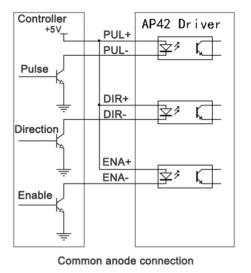
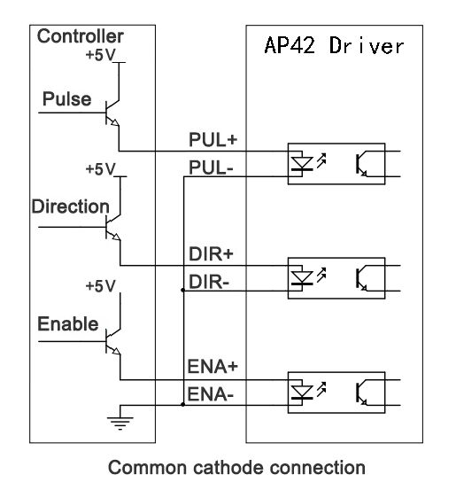
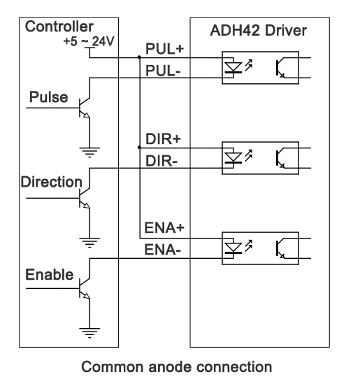
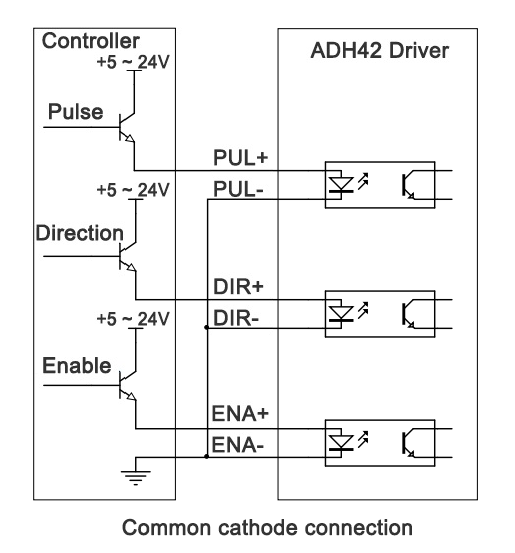
In addition to Differential wiring, AP42 Driver also supports common anode connection and common cathode connection:
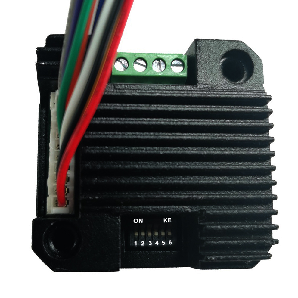
Dip Switch Settings:
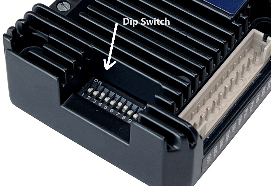
SW1 SW2 SW3 set Current,
SW4 SW5 SW6 Set Micro-Step,
SW8 Set direction CW/CCW.
SW9 SW10, Choose Working Mode
1. Set working current by SW1, SW2, SW3:
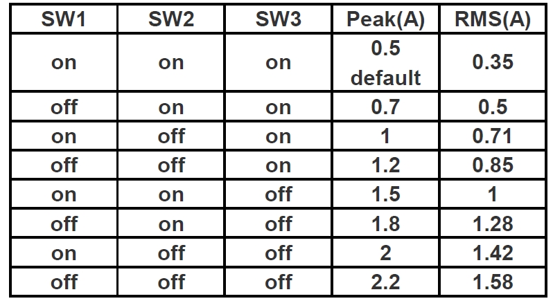
The default peak current at the factory is 0.5A, can be set through the serial port before sale,
The adjustable current range is any value between 0.1A and 2.2A (peak).
Set Stepper Motor's default rotation direction
SW8=on, CW
SW8=off, CCW
Note: the default rotation direction according to the wiring,
Swap wiring phase A A-(or B B-) will change the rotation direction.
Set Working Mode by SW9, SW10:
SW9 | SW10 | Working Mode |
on | on | Spontaneous pulses |
on | off | self-test |
off | on | double pulse |
off | off | Pulse & Direction |
Set Micro-Step and working speed by SW4,SW5,SW6 SW7: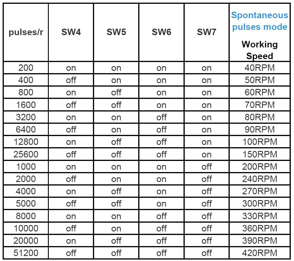
Note: set SW9,SW10 for Spontaneous pulses mode, working speed will be effective when connect the 5V pulse signal.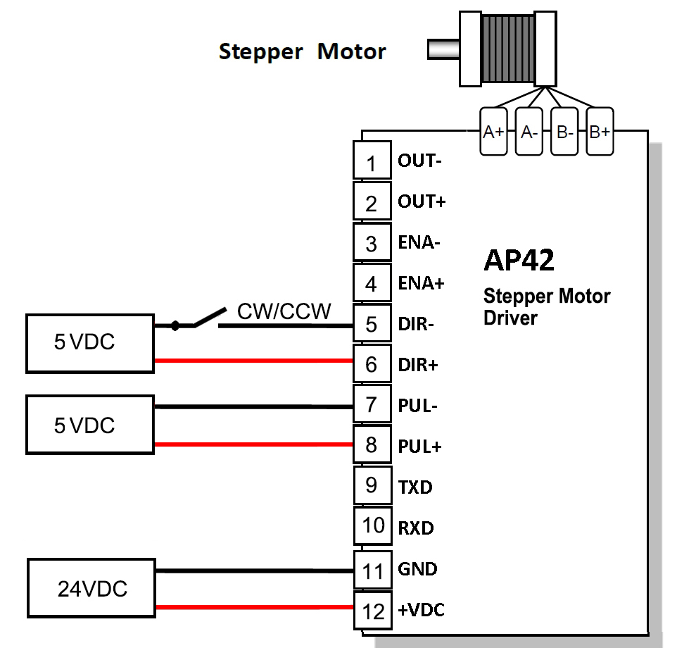
More Information on detail, please feel free to contact me

Pulse & direction stepper motor driver, support to Spontaneous pulses.
Spontaneous pulses Stepper Motor Driver
 | ADH42 | |||
minimum value | Typical value | Maximum value | Unit | |
Supply Voltage (DC) | 12 | 24 | 40 | VDC |
Control Signal | 7 | 10 | 16 | mA |
Step pulse frequency | 0 | - | 200 | KHz |
insulation resistance | 50 |
|
| MΩ |
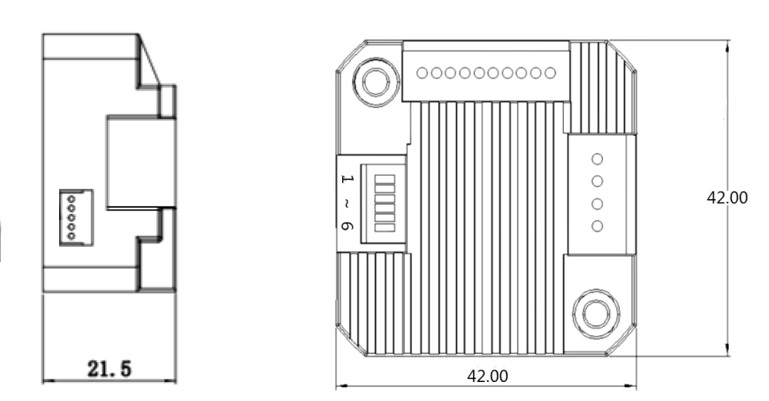
● Miniature size 42mmx42mm x21.5mm
● Pulse & direction stepper driver also support the standard RS232 serial command, and built-in 32bit digital chip.
● Using new control algorithms such for vibration suppression and low heat generation
● DC input voltage 12~40VDC, recommended working voltage 24VDC.
● Continuous output current 1.4A max, max peak current 2.1A.
● Integrated design, mounted with 42/39mm stepper motor.
● Low vibration, low noise, stable operation, low motor heating.
● Any micro-step can be set .
● Protection functions such as overvoltage, undervoltage and overcurrent.
● Built-in automatic matching function of motor parameter.
● ADM42H stepper driver can be assembled for NEMA17 Integrated Stepper Motors
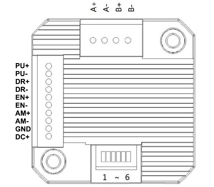
| Pin No. | Name | Description |
| 1 | PU | Pulse Control Signal Input: 5V ~ 24V, Rising Edge effective, Make sure pulse signal effective, pulse width ≥ 2μs Add the resistance for power supply. |
| 2 | PU- | |
| 3 | DR | Direction Signal: high/low level signal: 5V ~ 24V, direction signal should be at least 5 μs earlier than pulse signal, High/Low level. |
| 4 | DR- | |
| 5 | EN | Enable Signal:enable/disable. If ENA connect 5V & ENA- connect low level(or Internal optocoupler on), stepper controller will turn off the current, motor in free state, no feedback even send pulses. |
| 6 | EN- | |
| 7 | AM | Alarm signal output: When overvoltage, undervoltage, phase loss, or position deviation alarms occur, the alarm signal output is effective; Maximum driving current 50mA |
| 8 | AM- | |
| 9 | GND | Supply Voltage Ground: GND/0V |
| 10 | DC | Supply voltage: 12-40VDC, Recommend DC24V |
Wire support common anode connection and common cathode connection, controlled by PLC or Pulse Generators.
DIP Switch SW1 SW2 SW3 SW4 SW5 SW6 ↑
1. Set working current by SW1:
SW1 | Peak(A) | RMS(A) |
off | 1.4 | 1.0 |
on | 2.1 | 1.5 |
2. Set Working Mode by SW2:
SW2 | Working Mode |
off | Pulse & Direction |
on | Spontaneous pulses |
2.1. Pulse & Direction working mode:
Set Micro-step by SW3,SW4,SW5 SW6:
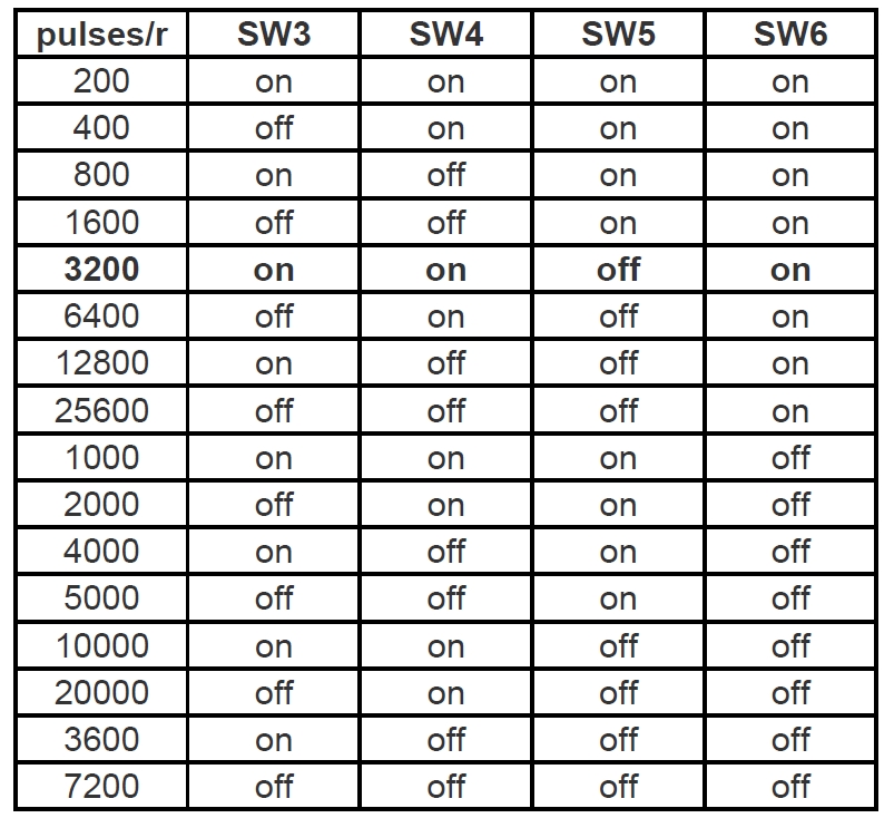
2.1. Spontaneous pulses working mode:
In this working mode, the PU PU- connect to the power supply 5~24VDC and GND,
make sure the stepper motors rotates instantly when power on, please check below wiring diagram:
Set Working Speed by SW3,SW4,SW5 SW6:
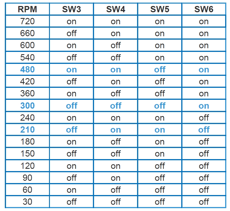
More Information on detail, please feel free to contact me