Search

Search Criteria


Products meeting the search criteria

Sort By:  
Hollow Shaft Stepper Motor
$36.00
Hollow Shaft Stepper Motor
$37.00
Hollow Shaft Stepper Motor
$50.00
Hollow Shaft Stepper Motor
$40.00
RS232 serial stepper motor controller
$120.00
ADH42 Stepper Motor Controller, Spontaneous pulse driver (ADH42)

Pulse & direction stepper motor driver, support to Spontaneous pulses.
Spontaneous pulses Stepper Motor Driver

ADH42

minimum value

Typical  value 

Maximum value

Unit  

Supply Voltage (DC)

12

24

40

VDC

Control Signal
input current

7

10

16

mA

Step pulse frequency

0

-

200

KHz

insulation resistance

50


● Miniature size 42mmx42mm x21.5mm

● Pulse & direction stepper driver also support the standard RS232 serial command, and built-in 32bit digital chip.

● Using new control algorithms such for vibration suppression and low heat generation

● DC input voltage 12~40VDC, recommended working voltage 24VDC.

● Continuous output current 1.4A max, max peak current 2.1A.

● Integrated design, mounted with 42/39mm stepper motor.

● Low vibration, low noise, stable operation, low motor heating.

● Any micro-step can be set .

● Protection functions such as overvoltage, undervoltage and overcurrent.

● Built-in automatic matching function of motor parameter.

● ADM42H stepper driver can be assembled for NEMA17 Integrated Stepper Motors


Pin No.  Name  Description
1PUPulse Control Signal Input:  5V ~ 24V, Rising Edge effective, 
Make sure pulse signal effective, pulse width ≥ 2μs
Add the resistance for power supply.
2PU-
3DRDirection Signal: high/low level signal: 5V ~ 24V, direction signal should be at least 5 μs earlier than pulse signal,  High/Low level.
4DR-
5EN  Enable Signal:enable/disable.
  If ENA  connect 5V & ENA- connect low level(or Internal optocoupler on), 
stepper controller will turn off the current, motor in free state, no feedback 
even send pulses.  
6EN-
7AMAlarm signal output: When overvoltage, undervoltage, phase loss, or position deviation alarms occur, the alarm signal output is effective;
Maximum driving current 50mA
8AM-
9GNDSupply Voltage Ground: GND/0V
10DC Supply voltage:  12-40VDC, Recommend DC24V

Wire support common anode connection and common cathode connection, controlled by PLC or Pulse Generators.


DIP Switch SW1 SW2 SW3 SW4 SW5 SW6 ↑

1. Set working current by SW1:

SW1

Peak(A)

RMS(A)

off

1.4

1.0

on

2.1

1.5


2. Set Working Mode by SW2:

SW2

Working Mode

off

Pulse & Direction

on

Spontaneous pulses


 2.1.  Pulse & Direction working mode:
        Set Micro-step by SW3,SW4,SW5 SW6:


 2.1.  Spontaneous pulses working mode:
         In this working mode, the PU PU- connect to the power supply 5~24VDC
and GND,
         make sure the stepper motors rotates instantly when power on, please check below wiring diagram:

         Set Working Speed by SW3,SW4,SW5 SW6:


More Information on detail, please feel free to contact me  
Spontaneous pulse driver
$58.00
NEMA6 Hollow Shaft Stepper Motor, 14mm Stepper Motor (6hs)


Step Accuracy:±5%Resistance Accuracy:±10%
Inductance Accuracy:±20%Temperature Rise:80°C MAX
Ambient Temperature Range: -20°C~ 50°CStorage Temperature Range: -30°C~ 60°C
Insulation Resistance:100M Ω MIN. 500V DCDielectric Strength:500V AC 1min
Radial Play:0.02mm MAX. (450g Load)End Play:0.08mm MAX. (450g Load)
Max. Radial Force:20NMax. Axial Force:2N

NEMA6 Hollow Shaft Stepper Motor

Electrical Specifications:

Model No.

Step

 Angle

Motor

Length 

(mm)

Rated
 voltage
(v)
Rated
  Current 
(A)
Phase
Resistance 
(Ω)
Phase
 Indutance 
(Mh)
Holding
Torque(MIN) 
N.m
Detent
Toruue(MAX)
N.cm

Motor

  Torque  

(g.cm2)

6HS20301.8326.60.3223.60.0050.0022.5

 Mechanical Dimensions and Wiring Diagram:

Torque Performance Curve: 

Lead Wire Mode Options:


More Information on detail, please feel free to contact me  

Hollow Shaft Stepper Motor
$80.00
NEMA8 Hollow Shaft Stepper Motor, 20mm Stepper Motor (8hs)


Step Accuracy:±5%Resistance Accuracy:±10%
Inductance Accuracy:±20%Temperature Rise:80°C MAX
Ambient Temperature Range: -20°C~ 50°CStorage Temperature Range: -30°C~ 60°C
Insulation Resistance:100M Ω MIN. 500V DCDielectric Strength:500V AC 1min
Radial Play:0.02mm MAX. (450g Load)End Play:0.08mm MAX. (450g Load)
Max. Radial Force:20NMax. Axial Force:2N

NEMA8 Hollow Shaft Stepper Motor

Electrical Specifications:

Model No.

Step

 Angle

Motor

Length 

(mm)

Rated
 voltage
(v)
Rated
  Current 
(A)
Phase
Resistance 
(Ω)
Phase
 Indutance 
(Mh)
Holding
Torque(MIN) 
N.cm
Detent
Toruue(MAX)
N.cm

Motor

  Torque  

(g.cm2)

Lead
 Wire  
Motor
 Weight
(g)
8HS20281.827.22.550.55.11.51.40.22.5450
8HS20381.828.14.40.58.82.72.00.24.5470

 Mechanical Dimensions and Wiring Diagram:

Torque Performance Curve: 

Lead Wire Mode Options:

More Information on detail, please feel free to contact me  

Hollow Shaft Stepper Motor
$35.00
NEMA14 Hollow Shaft Stepper Motor (14hs)


Step Accuracy:±5%Resistance Accuracy:±10%
Inductance Accuracy:±20%Temperature Rise:80°C MAX
Ambient Temperature Range: -20°C~ 50°CStorage Temperature Range: -30°C~ 60°C
Insulation Resistance:100M Ω MIN. 500V DCDielectric Strength:500V AC 1min
Radial Play:0.02mm MAX. (450g Load)End Play:0.08mm MAX. (450g Load)
Max. Radial Force:20NMax. Axial Force:2N

NEMA14 Hollow Shaft Stepper Motor

Electrical Specifications:

Model No.

Step

 Angle

Motor

Length 

(mm)

Rated
 voltage
(v)
Rated
  Current 
(A)
Phase
Resistance 
(Ω)
Phase
 Indutance 
(Mh)
Holding
Torque(MIN) 
N.cm
Detent
Toruue(MAX)
N.cm
Lead
 Wire  
14HS20331.833.63.51.03.53.6190.84
14HS20451.845.66.01.06.07.2361.34

 Mechanical Dimensions and Wiring Diagram:


Torque Performance Curve: 


Lead Wire Mode Options:


More Information on detail, please feel free to contact me  

Hollow Shaft Stepper Motor
$36.00
NEMA17 Hollow Shaft Stepper Motor (17hs)


Step Accuracy:±5%Resistance Accuracy:±10%
Inductance Accuracy:±20%Temperature Rise:80°C MAX
Ambient Temperature Range: -20°C~ 50°CStorage Temperature Range: -30°C~ 60°C
Insulation Resistance:100M Ω MIN. 500V DCDielectric Strength:500V AC 1min
Radial Play:0.02mm MAX. (450g Load)End Play:0.08mm MAX. (450g Load)
Max. Radial Force:20NMax. Axial Force:2N

NEMA17 Hollow Shaft Stepper Motor

Electrical Specifications:

Model No.

Step

 Angle

Motor

Length 

(mm)

Rated
 voltage
(v)
Rated
  Current 
(A)
Phase
Resistance 
(Ω)
Phase
 Indutance 
(Mh)
Holding
Torque(MIN) 
N.cm
Weight
(KG)
Inertia
(g*cm2)  
17HS12351.8353.81.22.14.270.2435
17HS20491.8492.52.01.353.2480.3677

 Mechanical Dimensions and Wiring Diagram:


Torque Performance Curve: 


Lead Wire Mode Options:


More Information on detail, please feel free to contact me  

Hollow Shaft Stepper Motor
$37.00
NEMA34 Hollow Shaft Stepper Motor (34hs)


Step Accuracy:±5%Resistance Accuracy:±10%
Inductance Accuracy:±20%Temperature Rise:80°C MAX
Ambient Temperature Range: -20°C~ 50°CStorage Temperature Range: -30°C~ 60°C
Insulation Resistance:100M Ω MIN. 500V DCDielectric Strength:500V AC 1min
Radial Play:0.02mm MAX. (450g Load)End Play:0.08mm MAX. (450g Load)
Max. Radial Force:20NMax. Axial Force:2N

NEMA34 Hollow Shaft Stepper Motor

Electrical Specifications:

Model No.

Step

 Angle

Motor

Length 

(mm)

Rated
  Current 
(A)
Phase
Resistance 
(Ω)
Phase
 Indutance 
(Mh)
Holding
Torque(MIN) 
N.m

Rated

Voltage

v

Detent

Torque

(N.m) 

34HS20761.876.03.01.9194.55.70.095

 Mechanical Dimensions and Wiring Diagram:


Torque Performance Curve: 


Lead Wire Mode Options:


More Information on detail, please feel free to contact me  

Hollow Shaft Stepper Motor
$50.00
NEMA11 Hollow Shaft Stepper Motor, 28mm Stepper Motor (11hs)

Step Accuracy:±5%Resistance Accuracy:±10%
Inductance Accuracy:±20%Temperature Rise:80°C MAX
Ambient Temperature Range: -20°C~ 50°CStorage Temperature Range: -30°C~ 60°C
Insulation Resistance:100M Ω MIN. 500V DCDielectric Strength:500V AC 1min
Radial Play:0.02mm MAX. (450g Load)End Play:0.08mm MAX. (450g Load)
Max. Radial Force:20NMax. Axial Force:2N

NEMA11 Hollow Shaft Stepper Motor

Electrical Specifications:

Model No.

Step

 Angle

Motor

Length 

(mm)

Rated
 voltage
(v)
Rated
  Current 
(A)
Phase
Resistance 
(Ω)
Phase
 Indutance 
(Mh)
Holding
Torque(MIN) 
N.cm
Detent
Toruue(MAX)
N.cm
Lead
 Wire  
11HS20331.833.52.11.02.11.55.30.44
11HS20451.845.04.11.04.14.011.70.44

 Mechanical Dimensions and Wiring Diagram:

Torque Performance Curve: 

Lead Wire Mode Options:


More Information on detail, please feel free to contact me  

Hollow Shaft Stepper Motor
$35.00
NEMA23 Hollow Shaft Stepper Motor (23hs)

Step Accuracy:±5%Resistance Accuracy:±10%
Inductance Accuracy:±20%Temperature Rise:80°C MAX
Ambient Temperature Range: -20°C~ 50°CStorage Temperature Range: -30°C~ 60°C
Insulation Resistance:100M Ω MIN. 500V DCDielectric Strength:500V AC 1min
Radial Play:0.02mm MAX. (450g Load)End Play:0.08mm MAX. (450g Load)
Max. Radial Force:20NMax. Axial Force:2N

NEMA23 Hollow Shaft Stepper Motor

Electrical Specifications:

Model No.

Step

 Angle

Motor

Length 

(mm)

Rated
  Current 
(A)
Phase
Resistance 
(Ω)
Phase
 Indutance 
(Mh)
Holding
Torque(MIN) 
N.m
Lead
 Wire  
Weight
(Kg)
23HS451.8452.01.754.10.840.6
23HS651.8654.00.72.02.140.8
23HS761.8764.00.652.52.041.1

 Mechanical Dimensions and Wiring Diagram:

Torque Performance Curve: 


Lead Wire Mode Options:


More Information on detail, please feel free to contact me  

Hollow Shaft Stepper Motor
$40.00
UIM241 RS232 Serial Stepper Motor Controller (UIM241)

UIM241 Series RS232 Serial Stepper Motor Controller

● Miniature size 42.3mmx42.3mm x14.5mm
● Integral design to fit motors, work standalone as well
● Wide range input voltage 10-40VDC
● 0-2A/ 1.5-4A/ 3-8A adjustable phase current
● 1 to 16th micro stepping
● Dual full H-bridge with PWM constant current control
● Accurate micro-stepping and current control
● Die-cast aluminum enclosure, improved heat dissipation and durability

Network Communication
-- RS232 three-wire serial communication
-- Max baud rate 57600 bps

Embedded DSP Microprocessor
-- Firmware DSP, 64bits calculating precision
-- Absolute position record / feedback, reset by instruction or sensor
-- Quadrature encoder based closed-loop control
-- Advanced motion control, linear and non-linear acceleration and deceleration, S-curve, PT/PVT displacement control
-- 2 sensor input ports
-- 8 programmable real-time event-based change notifications
-- 13 programmable actions triggered by 6 sensor events
-- Simple instructions
-- Intelligent control, intuitive and fault-tolerating


RS232 Serial Stepper Motor Controller Number Confirmation


Correspondence between Max. Supply Voltage and Peak Current

Max. Supply Voltage
Peak Current
  L: (DC28V)   C: (DC38V)  H: (DC48V)
      2A    √    √   √
      4A    ×    √    √
      8A    ×    √    √


Connector Type: P or T 


 P: P lug Socket (including cables)

                      T:  Screw Terminal

Model No. Example: UIM241L02T-MS; UIM241C04P-IE; UIM241C08T-E.


UIM241 RS232 Serial Stepper Motor Controller Wiring Terminal


Typical application of RS232 Serial Stepper Motor Controller


Video guidance for UIM241 Series Stepper Motor Controller


Software StepEva   Manual  


Support to Send Simple RS232 serial command Lists:

More Information on detail, please feel free to contact me  

RS232 serial stepper motor controller
$120.00
NEMA17 Integrated Stepper Motor with Multi-Turn Absolute Encoder (IS1705A)


The IS17A series integrated motor is the perfect combination of drive and stepper motor,
which perfectly integrates stepper motor and drive technology, also built in a battery free
1023 turn mechanical absolute value encoder, it can save installation space,
Simultaneously saving design and production costs, supporting RS485 instruction control.

ItemSpecifications
Stepper Motor SizeNEMA17
Encoder type1023 ring absolute encoder
Working voltage8-50VDC,  Recommend  DC36V
Driver Current0.2-3.2A
Velocity rangeUp to 3000RPM
Control MethodRS485 √   Pulse& Direction, Twin-Pulse, 
I/O,   Built-in Program
Torque value0.2 - 6Nm
Nonvolatile storageConfiguration parameters are stored in FLASH inside the MCU
DI and DO
2 DI, 1 DO
ProtectionOvervoltage, undervoltage, overcurrent, open winding, position deviation


Digital Input (2) Receive 3.3-24VDC
Digital Output(1)Maximum withstand voltage of 30V,
Maximum input or output current 30mA
Accuracy4000 pulses/r

Motor Parameters

Model No.length
mm L
Shaft length
mm
Shaft dia.
mm
Phase current
A
Resistance
Ω
inductance
mH
Hold torque
N.m
Inertia
g.cm²
Weight
g
IS1704642452.02.04.20.457380
IS1705722452.01.32.90.582460
IS1706842452.51.33.20.6116700


     Wiring Diagram:


    Terminal Definition

    TerminalNameDescription
    1V8-48VDC
    2V-GND
    3X0 (PU )Optoelectronic isolation, differential,
    High level can directly receive 3.3-24VDC, with a minimum pulse width of 2us,
    The maximum pulse frequency is 400KHz, which can be used as a universal input port or a high-speed pulse input port
    4X0-(PU-)
    5X1 (DR )
    6X1-(DR-)
    7485A(EN )RS485 Communication port, default baud rate is 115200,
     8485B(EN-)
    9Y0 (AL )The default alarm output port can detect the driver alarm status and provide feedback to the main station. Other functions can be set through communication
    10Y0-(AL-)

    Set Device ID by SW1, SW2, SW3, SW4 and SW5


    SW6 is used to set the terminal resistance;   OFF=0 ohms; ON=120 ohms

    Block Diagram:

    2  Input signals can directly receive 3.3-24V DC levels at high levels, Max. frequency of 400KHZ.
    X0:  pulse input, IO start/stop, limit, direction, universal input.
    X1  pulse input, IO start/stop, limit, direction, universal input.


    1 Output signal, maximum withstand voltage 30V, maximum input or output current 30mA
     Y0 : alarm output, universal output, and factory default alarm output.

    LED indicator and status:


    CRC Check routine by C# :

    Uint16 Funct_CRC16(unsigned char * puchMsg, Uint16 DataLen)
    {
    Uint16 i,j,tmp;
    Uint16 crcdata=0xFFFF;
    for(i=0;i<DataLen;i )
    {

    crcdata=(*puchMsg)^crcdata;
    puchMsg ;
    for(j=0;j<8;j )
    {
    tmp=crcdata&0x0001;
    crcdata=crcdata>>1;
    if(tmp){
    crcdata=crcdata^0xA001;
    }
    }
    }
    returncrcdata;
    }

    Software Modbus Poll 

    Software Step-Config
    1. Extract the zip file,  open CommFile and Click Step-Config.exe


    2. Right Click Modbus_485, and Click Property:
         
    3. Click Property ComNN, Choose COM port, Baud rate and click Save and OK.
       

    4. Start to use software control the RS485 Integrated stepper motor by below buttons:


    RS485 Stepper Motor Controller Manual 

    ~~~~~~~~~~~~~~~~~~~~~~~~~~~~~~~~~~~~~~~~~~~~~~~~~~~~~~~~~~~~~~~~~~~~~~~~~~~~~~~~~~~~
    Block Diagram:

    2  Input signals can directly receive 3.3-24V DC levels at high levels, Max. frequency of 400KHZ.
    X0:  pulse input, IO start/stop, limit, direction, universal input.
    X1  pulse input, IO start/stop, limit, direction, universal input.
    ...

    1 Output signal, maximum withstand voltage 30V, maximum input or output current 30mA
     Y0 : alarm output, universal output, and factory default alarm output.
     
    LED indicator and status:


    more Information on detail, please feel free to contact me  

    multi-ring absolute encoder
    $350.00
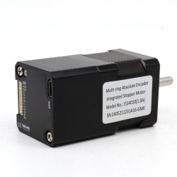
    NEMA14 Integrated Stepper Motor with Multi-turn Absolute Encoder (IS14010)


    The IS14 series integrated motor is the perfect combination of drive and stepper motor,
    which perfectly integrates stepper motor and drive technology, also built in a battery free
    1023 turn mechanical absolute value encoder, it can save installation space,
    Simultaneously saving design and production costs, supporting RS485 instruction control.

    ItemSpecifications
    Stepper Motor SizeNEMA14
    Encoder type1023 ring absolute encoder
    Working voltage8-36V
    Driver Current0.2-2.0A
    Velocity rangeUp to 3000RPM
    Control MethodRS485 √   Pulse& Direction, Twin-Pulse, 
    I/O,   Built-in Program
    Torque value0.1 - 0.4Nm
    Nonvolatile storageConfiguration parameters are stored in FLASH inside the MCU
    DI and DO
    2 DI, 1 DO
    ProtectionOvervoltage, undervoltage, overcurrent, open winding, position deviation


    Digital Input (2) Receive 3.3-24VDC
    Digital Output(1)Maximum withstand voltage of 30V,
    Maximum input or output current 30mA

    Motor Parameters

    Model No.length
    mm L
    Shaft length
    mm
    Shaft dia.
    mm
    Phase current
    A
    Resistance
    Ω
    inductance
    mH
    Hold torque
    N.m
    Inertia
    g.cm²
    Weight
    g
    IS14010522451.02.552.00.112240
    IS14020622451.51.652.10.220300
    IS14040802451.81.852.80.435350


       Wiring Diagram:


      Terminal Definition

      TerminalNameDescription
      1V8-36VDC
      2V-GND
      3X0 (PU )Optoelectronic isolation, differential,
      High level can directly receive 3.3-24VDC, with a minimum pulse width of 2us,
      The maximum pulse frequency is 400KHz, which can be used as a universal input port for Pulse/Direction
      4X0-(PU-)
      5X1 (DR )
      6X1-(DR-)
      7X2(EN )Optoelectronic isolation, differential,
      High level can directly receive 3.3-24VDC, with a minimum pulse width of 100us,
      The maximum pulse frequency is 10KHz, which can be used as a universal input port for Enable
       8X2-(EN-)
      9Y0 (AL )The default alarm output port can detect the driver alarm status and provide feedback to the main station. Other functions can be set through communication
      10Y0-(AL-)
      11485ARS485 Communication port, default baud rate is 115200
      12485B

      Block Diagram:

      2  Input signals can directly receive 3.3-24V DC levels at high levels, Max. frequency of 400KHZ.
      X0:  pulse input, IO start/stop, limit, direction, universal input.
      X1  pulse input, IO start/stop, limit, direction, universal input.


      1 Output signal, maximum withstand voltage 30V, maximum input or output current 30mA
       Y0 : alarm output, universal output, and factory default alarm output.

      LED indicator and status:


      CRC Check routine by C# :

      Uint16 Funct_CRC16(unsigned char * puchMsg, Uint16 DataLen)
      {
      Uint16 i,j,tmp;
      Uint16 crcdata=0xFFFF;
      for(i=0;i<DataLen;i )
      {

      crcdata=(*puchMsg)^crcdata;
      puchMsg ;
      for(j=0;j<8;j )
      {
      tmp=crcdata&0x0001;
      crcdata=crcdata>>1;
      if(tmp){
      crcdata=crcdata^0xA001;
      }
      }
      }
      returncrcdata;
      }

      Software Modbus Poll 

      Software Step-Config
      1. Extract the zip file,  open CommFile and Click Step-Config.exe


      2. Right Click Modbus_485, and Click Property:
           
      3. Click Property ComNN, Choose COM port, Baud rate and click Save and OK.
         

      4. Start to use software control the RS485 Integrated stepper motor by below buttons:


      RS485 Stepper Motor Controller Manual 

      ~~~~~~~~~~~~~~~~~~~~~~~~~~~~~~~~~~~~~~~~~~~~~~~~~~~~~~~~~~~~~~~~~~~~~~~~~~~~~~~~~~~~
      Block Diagram:

      2  Input signals can directly receive 3.3-24V DC levels at high levels, Max. frequency of 400KHZ.
      X0:  pulse input, IO start/stop, limit, direction, universal input.
      X1  pulse input, IO start/stop, limit, direction, universal input.
      ...

      1 Output signal, maximum withstand voltage 30V, maximum input or output current 30mA
       Y0 : alarm output, universal output, and factory default alarm output.
       
      LED indicator and status:


      more Information on detail, please feel free to contact me  

      multi-ring absolute encoder
      $350.00
      NEMA17 Closed Loop Integrated Stepper Motor (IG1705)


      The IG17 series integrated motor is the perfect combination of drive and stepper motor,
      which perfectly integrates stepper motor and drive technology, also built in 1000 line encoder,
      it can save installation space, Simultaneously saving design and production costs,
      supporting RS485 and TTL communication.

      ItemSpecifications
      Stepper Motor SizeNEMA17
      Encoder type1000 line encoder
      Working voltage8-50VDC,  Recommend  DC36V
      Driver Current0.2-3.2A
      Velocity rangeUp to 3000RPM
      Control MethodRS485,  Pulse& Direction, Twin-Pulse, 
      I/O,   Built-in Program
      Torque value0.2 - 6Nm
      Nonvolatile storageConfiguration parameters are stored in FLASH inside the MCU
      DI and DO
      2 DI, 1 DO
      ProtectionOvervoltage, undervoltage, overcurrent, open winding, position deviation

      Digital Input (2/3) Receive 3.3-24VDC
      Digital Output(1)Maximum withstand voltage of 30V,
      Maximum input or output current 30mA


      Motor Parameters

      Model No.length
      mm L
      Shaft length
      mm
      Shaft dia.
      mm
      Phase current
      A
      Resistance
      Ω
      inductance
      mH
      Hold torque
      N.m
      Inertia
      g.cm²
      Weight
      g
      IG1704402182.024.20.457380
      IG1705482182.01.32.90.582460
      IG1706602182.51.33.20.6116700


         Wiring Diagram:
        ~~~~~~~~~~~~~~~~~~~~~~~~~~~~~~~~~~~~~~~~~~~~~~~~~~~~~~~~~~~~~~~~~~~~~~~~~~~~~~~~~~~~~~~~~~~
        1. Pulse Type Integrated Stepper Motor, Terminal definition.
         

        Terminal Definition

        TerminalNameDescription
        1V8-48VDC
        2V-GND
        3X0 (PU )Optoelectronic isolation, differential,
        High level can directly receive 3.3-24VDC, with a minimum pulse width of 2us,
        The maximum pulse frequency is 400KHz, which can be used as a universal input port for Pulse/Direction
        4X0-(PU-)
        5X1 (DR )
        6X1-(DR-)
        7X2(EN )Optoelectronic isolation, differential,
        High level can directly receive 3.3-24VDC, with a minimum pulse width of 100us,
        The maximum pulse frequency is 10KHz, which can be used as a universal input port for Enable
         8X2(EN-)
        9Y0 (AL )The default alarm output port can detect the driver alarm status and provide feedback to the main station. Other functions can be set through communication
        10Y0-(AL-)

        Set Micro-step by SW1, SW2, SW3 and SW4:


        SW5=OFF:  Pulse & Direction;   SW=ON: Twin Pulse mode.
        SW6=OFF:  CW direction;  SW6=ON:  CCW direction.

        ~~~~~~~~~~~~~~~~~~~~~~~~~~~~~~~~~~~~~~~~~~~~~~~~~~~~~~~~~~~~~~~~~~~~~~~~~~~~~~~~~~~~~~~~~
        2. RS485 Type Integrated Stepper Motor, Terminal definition.

        Terminal Definition

        TerminalNameDescription
        1V8-48VDC
        2V-GND
        3X0 (PU )Optoelectronic isolation, differential,
        High level can directly receive 3.3-24VDC, with a minimum pulse width of 2us,
        The maximum pulse frequency is 400KHz, which can be used as a universal input port or a high-speed pulse input port
        4X0-(PU-)
        5X1 (DR )
        6X1-(DR-)
        7485A(EN )RS485 Communication port, default baud rate is 115200,
         8485B(EN-)
        9Y0 (AL )The default alarm output port can detect the driver alarm status and provide feedback to the main station. Other functions can be set through communication
        10Y0-(AL-)

        Set Device ID for RS485 integrated Stepper Motor by SW1 ~ SW5:


        SW6 is used to set the terminal resistance;   OFF=0 ohms; ON=120 ohms

        CRC Check routine by C# :

        Uint16 Funct_CRC16(unsigned char * puchMsg, Uint16 DataLen)
        {
        Uint16 i,j,tmp;
        Uint16 crcdata=0xFFFF;
        for(i=0;i<DataLen;i )
        {

        crcdata=(*puchMsg)^crcdata;
        puchMsg ;
        for(j=0;j<8;j )
        {
        tmp=crcdata&0x0001;
        crcdata=crcdata>>1;
        if(tmp){
        crcdata=crcdata^0xA001;
        }
        }
        }
        returncrcdata;
        }

        Software Modbus Poll 

        Software Step-Config
        1. Extract the zip file,  open CommFile and Click Step-Config.exe


        2. Right Click Modbus_485, and Click Property:
             
        3. Click Property ComNN, Choose COM port, Baud rate and click Save and OK.
           

        4. Start to use software control the RS485 Integrated stepper motor by below buttons:


        RS485 Stepper Motor Controller Manual 

        ~~~~~~~~~~~~~~~~~~~~~~~~~~~~~~~~~~~~~~~~~~~~~~~~~~~~~~~~~~~~~~~~~~~~~~~~~~~~~~~~~~~~
        Block Diagram:

        2  Input signals can directly receive 3.3-24V DC levels at high levels, Max. frequency of 400KHZ.
        X0:  pulse input, IO start/stop, limit, direction, universal input.
        X1  pulse input, IO start/stop, limit, direction, universal input.
        ...

        1 Output signal, maximum withstand voltage 30V, maximum input or output current 30mA
         Y0 : alarm output, universal output, and factory default alarm output.
         
        LED indicator and status:


        more Information on detail, please feel free to contact me  

        RS485 and Pulse Type
        $80.00
        NEMA23 Closed Loop Integrated Stepper Motor (IG2312)


        The IG23 series integrated motor is the perfect combination of drive and stepper motor,
        which perfectly integrates stepper motor and drive technology, also built in 1000 line encoder,
        it can save installation space, Simultaneously saving design and production costs,
        supporting RS485 and TTL communication.

        ItemSpecifications
        Stepper Motor SizeNEMA23
        Encoder type1000 line encoder
        Working voltage8-60VDC,  Recommend  DC36V
        Driver Current0.5-5A
        Velocity rangeUp to 3000RPM
        Control MethodRS485,  Pulse& Direction, Twin-Pulse, 
        I/O,   Built-in Program
        Torque value0.8 - 2.2Nm
        Nonvolatile storageConfiguration parameters are stored in FLASH inside the MCU
        DI and DO
        2 DI, 1 DO
        ProtectionOvervoltage, undervoltage, overcurrent, open winding, position deviation

        Digital Input (2/3) Receive 3.3-24VDC
        Digital Output(1)Maximum withstand voltage of 30V,
        Maximum input or output current 30mA


        Motor Parameters

        Model No.length
        mm L
        Shaft length
        mm
        Shaft dia.
        mm
        Phase current
        A
        Resistance
        Ω
        inductance
        mH
        Hold torque
        N.m
        Inertia
        g.cm²
        Weight
        g
        IG23126821840.51.81.2280800
        IG23208521850.42.02.04801100


           Wiring Diagram:
          ~~~~~~~~~~~~~~~~~~~~~~~~~~~~~~~~~~~~~~~~~~~~~~~~~~~~~~~~~~~~~~~~~~~~~~~~~~~~~~~~~~~~~~~~~~~
          1. Pulse Type Integrated Stepper Motor, Terminal definition.
           

          Terminal Definition

          TerminalNameDescription
          1V24~60VDC
          2V-GND
          3X0 (PU )Optoelectronic isolation, differential,
          High level can directly receive 3.3-24VDC, with a minimum pulse width of 2us,
          The maximum pulse frequency is 400KHz, which can be used as a universal input port for Pulse/Direction
          4X0-(PU-)
          5X1 (DR )
          6X1-(DR-)
          7X2(EN )Optoelectronic isolation, differential,
          High level can directly receive 3.3-24VDC, with a minimum pulse width of 100us,
          The maximum pulse frequency is 10KHz, which can be used as a universal input port for Enable
           8X2(EN-)
          9Y0 (AL )The default alarm output port can detect the driver alarm status and provide feedback to the main station. Other functions can be set through communication
          10Y0-(AL-)
          11Y1(EX )The default In-place output , Other functions can be set through communication
          12Y1(EX-)

          Set Micro-step by SW1, SW2, SW3 and SW4:


          SW5=OFF:  Pulse & Direction;   SW=ON: Twin Pulse mode.
          SW6=OFF:  CW direction;  SW6=ON:  CCW direction.

          ~~~~~~~~~~~~~~~~~~~~~~~~~~~~~~~~~~~~~~~~~~~~~~~~~~~~~~~~~~~~~~~~~~~~~~~~~~~~~~~~~~~~~~~~~
          2. RS485 Type Integrated Stepper Motor, Terminal definition.

          Terminal Definition

          TerminalNameDescription
          1V24~60VDC
          2V-GND
          3X0 (PU )Optoelectronic isolation, differential,
          High level can directly receive 3.3-24VDC, with a minimum pulse width of 2us,
          The maximum pulse frequency is 400KHz, which can be used as a universal input port for Pulse/Direction/Enable
          4X0-(PU-)
          5X1 (DR )
          6X1-(DR-)
          7X2 (EN )
           8X2-(EN-)
          9Y0 (AL )The default alarm output port can detect the driver alarm status and provide feedback to the main station. Other functions can be set through communication
          10Y0-(AL-)
          11485ARS485 Communication port, default baud rate is 115200
          12485B

          Set Device ID for RS485 integrated Stepper Motor by SW1 ~ SW5:


          SW6 is used to set the terminal resistance;   OFF=0 ohms; ON=120 ohms

          CRC Check routine by C# :

          Uint16 Funct_CRC16(unsigned char * puchMsg, Uint16 DataLen)
          {
          Uint16 i,j,tmp;
          Uint16 crcdata=0xFFFF;
          for(i=0;i<DataLen;i )
          {

          crcdata=(*puchMsg)^crcdata;
          puchMsg ;
          for(j=0;j<8;j )
          {
          tmp=crcdata&0x0001;
          crcdata=crcdata>>1;
          if(tmp){
          crcdata=crcdata^0xA001;
          }
          }
          }
          returncrcdata;
          }

          Software Modbus Poll 

          Software Step-Config
          1. Extract the zip file,  open CommFile and Click Step-Config.exe


          2. Right Click Modbus_485, and Click Property:
               
          3. Click Property ComNN, Choose COM port, Baud rate and click Save and OK.
             

          4. Start to use software control the RS485 Integrated stepper motor by below buttons:


          RS485 Stepper Motor Controller Manual 

          ~~~~~~~~~~~~~~~~~~~~~~~~~~~~~~~~~~~~~~~~~~~~~~~~~~~~~~~~~~~~~~~~~~~~~~~~~~~~~~~~~~~~
          Block Diagram:

          2  Input signals can directly receive 3.3-24V DC levels at high levels, Max. frequency of 400KHZ.
          X0:  pulse input, IO start/stop, limit, direction, universal input.
          X1  pulse input, IO start/stop, limit, direction, universal input.
          ...

          1 Output signal, maximum withstand voltage 30V, maximum input or output current 30mA
           Y0 : alarm output, universal output, and factory default alarm output.
           
          LED indicator and status:


          more Information on detail, please feel free to contact me  

          RS485 and Pulse Type
          $98.00
          NEMA24 Closed Loop Integrated Stepper Motor (IG2422)


          The IG23 series integrated motor is the perfect combination of drive and stepper motor,
          which perfectly integrates stepper motor and drive technology, also built in 1000 line encoder,
          it can save installation space, Simultaneously saving design and production costs,
          supporting RS485 and TTL communication.

          ItemSpecifications
          Stepper Motor SizeNEMA24
          Encoder type1000 line encoder
          Working voltage24-60VDC
          Driver Current0.5-5A
          Velocity rangeUp to 3000RPM
          Control MethodRS485,  Pulse& Direction, Twin-Pulse, 
          I/O,   Built-in Program
          Torque value1.6 - 3.5Nm
          Nonvolatile storageConfiguration parameters are stored in FLASH inside the MCU
          DI and DO
          2 DI, 1 DO
          ProtectionOvervoltage, undervoltage, overcurrent, open winding, position deviation

          Digital Input (2/3) Receive 3.3-24VDC
          Digital Output(1)Maximum withstand voltage of 30V,
          Maximum input or output current 30mA


          Motor Parameters

          Model No.length
          mm L
          Shaft length
          mm
          Shaft dia.
          mm
          Phase current
          A
          Resistance
          Ω
          inductance
          mH
          Hold torque
          N.m
          Inertia
          g.cm²
          Weight
          g
          IG24226821850.331.052.24901300
          IG24308521850.432.03.06901500


             Wiring Diagram:
            ~~~~~~~~~~~~~~~~~~~~~~~~~~~~~~~~~~~~~~~~~~~~~~~~~~~~~~~~~~~~~~~~~~~~~~~~~~~~~~~~~~~~~~~~~~~
            1. Pulse Type Integrated Stepper Motor, Terminal definition.
             

            Terminal Definition

            TerminalNameDescription
            1V24~60VDC
            2V-GND
            3X0 (PU )Optoelectronic isolation, differential,
            High level can directly receive 3.3-24VDC, with a minimum pulse width of 2us,
            The maximum pulse frequency is 400KHz, which can be used as a universal input port for Pulse/Direction
            4X0-(PU-)
            5X1 (DR )
            6X1-(DR-)
            7X2(EN )Optoelectronic isolation, differential,
            High level can directly receive 3.3-24VDC, with a minimum pulse width of 100us,
            The maximum pulse frequency is 10KHz, which can be used as a universal input port for Enable
             8X2(EN-)
            9Y0 (AL )The default alarm output port can detect the driver alarm status and provide feedback to the main station. Other functions can be set through communication
            10Y0-(AL-)
            11Y1(EX )The default In-place output , Other functions can be set through communication
            12Y1(EX-)

            Set Micro-step by SW1, SW2, SW3 and SW4:


            SW5=OFF:  Pulse & Direction;   SW=ON: Twin Pulse mode.
            SW6=OFF:  CW direction;  SW6=ON:  CCW direction.

            ~~~~~~~~~~~~~~~~~~~~~~~~~~~~~~~~~~~~~~~~~~~~~~~~~~~~~~~~~~~~~~~~~~~~~~~~~~~~~~~~~~~~~~~~~
            2. RS485 Type Integrated Stepper Motor, Terminal definition.

            Terminal Definition

            TerminalNameDescription
            1V24~60VDC
            2V-GND
            3X0 (PU )Optoelectronic isolation, differential,
            High level can directly receive 3.3-24VDC, with a minimum pulse width of 2us,
            The maximum pulse frequency is 400KHz, which can be used as a universal input port for Pulse/Direction/Enable
            4X0-(PU-)
            5X1 (DR )
            6X1-(DR-)
            7X2 (EN )
             8X2-(EN-)
            9Y0 (AL )The default alarm output port can detect the driver alarm status and provide feedback to the main station. Other functions can be set through communication
            10Y0-(AL-)
            11485ARS485 Communication port, default baud rate is 115200
            12485B

            Set Device ID for RS485 integrated Stepper Motor by SW1 ~ SW5:


            SW6 is used to set the terminal resistance;   OFF=0 ohms; ON=120 ohms

            CRC Check routine by C# :

            Uint16 Funct_CRC16(unsigned char * puchMsg, Uint16 DataLen)
            {
            Uint16 i,j,tmp;
            Uint16 crcdata=0xFFFF;
            for(i=0;i<DataLen;i )
            {

            crcdata=(*puchMsg)^crcdata;
            puchMsg ;
            for(j=0;j<8;j )
            {
            tmp=crcdata&0x0001;
            crcdata=crcdata>>1;
            if(tmp){
            crcdata=crcdata^0xA001;
            }
            }
            }
            returncrcdata;
            }

            Software Modbus Poll 

            Software Step-Config
            1. Extract the zip file,  open CommFile and Click Step-Config.exe


            2. Right Click Modbus_485, and Click Property:
                 
            3. Click Property ComNN, Choose COM port, Baud rate and click Save and OK.
               

            4. Start to use software control the RS485 Integrated stepper motor by below buttons:


            RS485 Stepper Motor Controller Manual 

            ~~~~~~~~~~~~~~~~~~~~~~~~~~~~~~~~~~~~~~~~~~~~~~~~~~~~~~~~~~~~~~~~~~~~~~~~~~~~~~~~~~~~
            Block Diagram:

            2  Input signals can directly receive 3.3-24V DC levels at high levels, Max. frequency of 400KHZ.
            X0:  pulse input, IO start/stop, limit, direction, universal input.
            X1  pulse input, IO start/stop, limit, direction, universal input.
            ...

            1 Output signal, maximum withstand voltage 30V, maximum input or output current 30mA
             Y0 : alarm output, universal output, and factory default alarm output.
             
            LED indicator and status:


            more Information on detail, please feel free to contact me  

            RS485 and Pulse Type
            $98.00
            NEMA34 Closed Loop Integrated Stepper Motor (IG3445)


            The IG23 series integrated motor is the perfect combination of drive and stepper motor,
            which perfectly integrates stepper motor and drive technology, also built in 1000 line encoder,
            it can save installation space, Simultaneously saving design and production costs,
            supporting RS485 and TTL communication.

            ItemSpecifications
            Stepper Motor SizeNEMA34
            Encoder type1000 line encoder
            Working voltage24~80VDC,  18~60VAC
            Driver Current0.5-6.5A
            Velocity rangeUp to 3000RPM
            Control MethodRS485,  Pulse& Direction, Twin-Pulse, 
            I/O,   Built-in Program
            Torque value3.5 -12.5Nm
            Nonvolatile storageConfiguration parameters are stored in FLASH inside the MCU
            DI and DO
            2 DI, 1 DO
            ProtectionOvervoltage, undervoltage, overcurrent, open winding, position deviation

            Digital Input (2/3) Receive 3.3-24VDC
            Digital Output(1)Maximum withstand voltage of 30V,
            Maximum input or output current 30mA


            Motor Parameters

            Model No.length
            mm L
            Shaft length
            mm
            Shaft dia.
            mm
            Phase current
            A
            Resistance
            Ω
            inductance
            mH
            Hold torque
            N.m
            Inertia
            g.cm²
            Weight
            g
            IG344580321460.53.64.519502900
            IG2346598321460.634.56.525003400
            IG3485118321460.54.28.528004100
            IG34125151321460.634.712.549505600


               Wiring Diagram:
              ~~~~~~~~~~~~~~~~~~~~~~~~~~~~~~~~~~~~~~~~~~~~~~~~~~~~~~~~~~~~~~~~~~~~~~~~~~~~~~~~~~~~~~~~~~~
              1. Pulse Type Integrated Stepper Motor, Terminal definition.
               

              Terminal Definition

              TerminalNameDescription
              1V24~60VDC
              2V-GND
              3X0 (PU )Optoelectronic isolation, differential,
              High level can directly receive 3.3-24VDC, with a minimum pulse width of 2us,
              The maximum pulse frequency is 400KHz, which can be used as a universal input port for Pulse/Direction
              4X0-(PU-)
              5X1 (DR )
              6X1-(DR-)
              7X2(EN )Optoelectronic isolation, differential,
              High level can directly receive 3.3-24VDC, with a minimum pulse width of 100us,
              The maximum pulse frequency is 10KHz, which can be used as a universal input port for Enable
               8X2(EN-)
              9Y0 (AL )The default alarm output port can detect the driver alarm status and provide feedback to the main station. Other functions can be set through communication
              10Y0-(AL-)
              11Y1(EX )The default In-place output , Other functions can be set through communication
              12Y1(EX-)

              Set Micro-step by SW1, SW2, SW3 and SW4:


              SW5=OFF:  Pulse & Direction;   SW=ON: Twin Pulse mode.
              SW6=OFF:  CW direction;  SW6=ON:  CCW direction.

              ~~~~~~~~~~~~~~~~~~~~~~~~~~~~~~~~~~~~~~~~~~~~~~~~~~~~~~~~~~~~~~~~~~~~~~~~~~~~~~~~~~~~~~~~~
              2. RS485 Type Integrated Stepper Motor, Terminal definition.

              Terminal Definition

              TerminalNameDescription
              1V24~60VDC
              2V-GND
              3X0 (PU )Optoelectronic isolation, differential,
              High level can directly receive 3.3-24VDC, with a minimum pulse width of 2us,
              The maximum pulse frequency is 400KHz, which can be used as a universal input port for Pulse/Direction
              4X0-(PU-)
              5X1 (DR )
              6X1-(DR-)
              7X2 (EN )
               8X2-(EN-)
              9Y0 (AL )The default alarm output port can detect the driver alarm status and provide feedback to the main station. Other functions can be set through communication
              10Y0-(AL-)
              11485ARS485 Communication port, default baud rate is 115200
              12485B

              Set Device ID for RS485 integrated Stepper Motor by SW1 ~ SW5:


              SW6 is used to set the terminal resistance;   OFF=0 ohms; ON=120 ohms

              CRC Check routine by C# :

              Uint16 Funct_CRC16(unsigned char * puchMsg, Uint16 DataLen)
              {
              Uint16 i,j,tmp;
              Uint16 crcdata=0xFFFF;
              for(i=0;i<DataLen;i )
              {

              crcdata=(*puchMsg)^crcdata;
              puchMsg ;
              for(j=0;j<8;j )
              {
              tmp=crcdata&0x0001;
              crcdata=crcdata>>1;
              if(tmp){
              crcdata=crcdata^0xA001;
              }
              }
              }
              returncrcdata;
              }

              Software Modbus Poll 

              Software Step-Config
              1. Extract the zip file,  open CommFile and Click Step-Config.exe


              2. Right Click Modbus_485, and Click Property:
                   
              3. Click Property ComNN, Choose COM port, Baud rate and click Save and OK.
                 

              4. Start to use software control the RS485 Integrated stepper motor by below buttons:


              RS485 Stepper Motor Controller Manual 

              ~~~~~~~~~~~~~~~~~~~~~~~~~~~~~~~~~~~~~~~~~~~~~~~~~~~~~~~~~~~~~~~~~~~~~~~~~~~~~~~~~~~~
              Block Diagram:

              2  Input signals can directly receive 3.3-24V DC levels at high levels, Max. frequency of 400KHZ.
              X0:  pulse input, IO start/stop, limit, direction, universal input.
              X1  pulse input, IO start/stop, limit, direction, universal input.
              ...

              1 Output signal, maximum withstand voltage 30V, maximum input or output current 30mA
               Y0 : alarm output, universal output, and factory default alarm output.
               
              LED indicator and status:


              more Information on detail, please feel free to contact me  

              RS485 and Pulse Type
              $101.00
              NEMA14 Closed Loop Integrated Stepper Motor (IG1412)


              The IG14 series integrated motor is the perfect combination of drive and stepper motor,
              which perfectly integrates stepper motor and drive technology, also built in 1000 line encoder,
              it can save installation space, Simultaneously saving design and production costs,
              supporting RS485 and TTL communication.

              ItemSpecifications
              Stepper Motor SizeNEMA14
              Encoder type1000 line encoder
              Working voltage8 ~ 36VDC
              Driver Current0.2-2.0A
              Velocity rangeUp to 3000RPM
              Control MethodRS485,  Pulse& Direction, Twin-Pulse, 
              I/O,   Built-in Program
              Torque value0.2 - 0.4Nm
              Nonvolatile storageConfiguration parameters are stored in FLASH inside the MCU
              DI and DO
              2/3 DI,  1 DO
              ProtectionOvervoltage, undervoltage, overcurrent, open winding, position deviation

              Digital Input (2/3) Receive 3.3-24VDC
              Digital Output(1)Maximum withstand voltage of 30V,
              Maximum input or output current 30mA


              Motor Parameters
              Pulse type NEMA14 integrated Stepper Motor:

              Model No.length
              mm L
              Shaft length
              mm
              Shaft dia.
              mm
              Phase current
              A
              Resistance
              Ω
              inductance
              mH
              Hold torque
              N.m
              Inertia
              g.cm²
              Weight
              g
              IG1418322451.51.51.60.1815200
              IG1425372451.51.52.00.2526250
              IG1440502451.81.12.50.4038350

              RS485 type NEMA14 integrated Stepper Motor:

              Model No.length
              mm L
              Shaft length
              mm
              Shaft dia.
              mm
              Phase current
              A
              Resistance
              Ω
              inductance
              mH
              Hold torque
              N.m
              Inertia
              g.cm²
              Weight
              g
              IG1412262451.01.51.90.128230
              IG1420342451.52.12.10.2014290
              IG1425402451.52.52.80.2520340
              IG1435532451.82.94.80.3531440


               Wiring Diagram:
              ~~~~~~~~~~~~~~~~~~~~~~~~~~~~~~~~~~~~~~~~~~~~~~~~~~~~~~~~~~~~~~~~~~~~~~~~~~~~~~~~~~~~~~~~~~~
              1. Pulse Type Integrated Stepper Motor, Terminal definition.
               

                Terminal Definition

                TerminalNameDescription
                1V8-48VDC
                2V-GND
                3X0 (PU )Optoelectronic isolation, differential,
                High level can directly receive 3.3-24VDC, with a minimum pulse width of 2us,
                The maximum pulse frequency is 400KHz, which can be used as a universal input port for Pulse/Direction
                4X0-(PU-)
                5X1 (DR )
                6X1-(DR-)
                7X2(EN )Optoelectronic isolation, differential,
                High level can directly receive 3.3-24VDC, with a minimum pulse width of 100us,
                The maximum pulse frequency is 10KHz, which can be used as a universal input port for Enable
                 8X2(EN-)
                9Y0 (AL )The default alarm output port can detect the driver alarm status and provide feedback to the main station. Other functions can be set through communication
                10Y0-(AL-)
                11Y1Default function is in-place output
                12Y1-


                ~~~~~~~~~~~~~~~~~~~~~~~~~~~~~~~~~~~~~~~~~~~~~~~~~~~~~~~~~~~~~~~~~~~~~~~~~~~~~~~~~~~~~~~~~
                2. RS485 Type Integrated Stepper Motor, Terminal definition.

                Terminal Definition

                TerminalNameDescription
                1V8-48VDC
                2V-GND
                3X0 (PU )Optoelectronic isolation, differential,
                High level can directly receive 3.3-24VDC, with a minimum pulse width of 2us,
                The maximum pulse frequency is 400KHz, which can be used as a universal input port or a high-speed pulse input port
                4X0-(PU-)
                5X1 (DR )
                6X1-(DR-)
                7X2
                8X2-
                9Y0 (AL )The default alarm output port can detect the driver alarm status and provide feedback to the main station. Other functions can be set through communication
                10Y0-(AL-)
                11485ARS485 Communication port, default baud rate is 115200,
                12485B

                CRC Check routine by C# :

                Uint16 Funct_CRC16(unsigned char * puchMsg, Uint16 DataLen)
                {
                Uint16 i,j,tmp;
                Uint16 crcdata=0xFFFF;
                for(i=0;i<DataLen;i )
                {

                crcdata=(*puchMsg)^crcdata;
                puchMsg ;
                for(j=0;j<8;j )
                {
                tmp=crcdata&0x0001;
                crcdata=crcdata>>1;
                if(tmp){
                crcdata=crcdata^0xA001;
                }
                }
                }
                returncrcdata;
                }

                Software Modbus Poll 

                Software Step-Config
                1. Extract the zip file,  open CommFile and Click Step-Config.exe


                2. Right Click Modbus_485, and Click Property:
                     
                3. Click Property ComNN, Choose COM port, Baud rate and click Save and OK.
                   

                4. Start to use software control the RS485 Integrated stepper motor by below buttons:


                RS485 Stepper Motor Controller Manual 

                ~~~~~~~~~~~~~~~~~~~~~~~~~~~~~~~~~~~~~~~~~~~~~~~~~~~~~~~~~~~~~~~~~~~~~~~~~~~~~~~~~~~~
                Block Diagram:

                2  Input signals can directly receive 3.3-24V DC levels at high levels, Max. frequency of 400KHZ.
                X0:  pulse input, IO start/stop, limit, direction, universal input.
                X1  pulse input, IO start/stop, limit, direction, universal input.
                ...

                1 Output signal, maximum withstand voltage 30V, maximum input or output current 30mA
                 Y0 : alarm output, universal output, and factory default alarm output.
                 
                LED indicator and status:


                more Information on detail, please feel free to contact me  

                RS485 and Pulse Type
                $80.00
                NEMA11 Closed Loop Integrated Stepper Motor (IG11008)


                The IG11 series integrated motor is the perfect combination of drive and stepper motor,
                which perfectly integrates stepper motor and drive technology, also built in 1000 line encoder,
                it can save installation space, Simultaneously saving design and production costs,
                supporting RS485 and TTL communication.

                ItemSpecifications
                Stepper Motor SizeNEMA11
                Encoder type1000 line encoder
                Working voltage8~36VDC
                Driver Current0.2-2.0A
                Velocity rangeUp to 3000RPM
                Control MethodRS485,  Pulse& Direction, Twin-Pulse, 
                I/O,   Built-in Program
                Torque value0.08 - 0.24Nm
                Nonvolatile storageConfiguration parameters are stored in FLASH inside the MCU
                DI and DO
                2/3 DI,  1 DO
                ProtectionOvervoltage, undervoltage, overcurrent, open winding, position deviation

                Digital Input (2/3) Receive 3.3-24VDC
                Digital Output(1)Maximum withstand voltage of 30V,
                Maximum input or output current 30mA


                Motor Parameters
                NEMA11 integrated Stepper Motor:

                Model No.length
                mm L
                Shaft length
                mm
                Shaft dia.
                mm
                Phase current
                A
                Resistance
                Ω
                inductance
                mH
                Hold torque
                N.m
                Inertia
                g.cm²
                Weight
                g
                IG11008312651.01.51.10.089115
                IG11018522651.32.42.30.1818205
                IG11024632651.51.82.10.2430268

                 Wiring Diagram:
                ~~~~~~~~~~~~~~~~~~~~~~~~~~~~~~~~~~~~~~~~~~~~~~~~~~~~~~~~~~~~~~~~~~~~~~~~~~~~~~~~~~~~~~~~~~~
                1. Pulse Type Integrated Stepper Motor, Terminal definition.
                 

                  Terminal Definition

                  TerminalNameDescription
                  1V8-36VDC
                  2V-GND
                  3X0 (PU )Optoelectronic isolation, differential,
                  High level can directly receive 3.3-24VDC, with a minimum pulse width of 2us,
                  The maximum pulse frequency is 400KHz, which can be used as a universal input port for Pulse/Direction
                  4X0-(PU-)
                  5X1 (DR )
                  6X1-(DR-)
                  7X2(EN )Optoelectronic isolation, differential,
                  High level can directly receive 3.3-24VDC, with a minimum pulse width of 100us,
                  The maximum pulse frequency is 10KHz, which can be used as a universal input port for Enable
                   8X2(EN-)
                  9Y0 (AL )The default alarm output port can detect the driver alarm status and provide feedback to the main station. Other functions can be set through communication
                  10Y0-(AL-)
                  11Y1Default function is in-place output
                  12Y1-


                  ~~~~~~~~~~~~~~~~~~~~~~~~~~~~~~~~~~~~~~~~~~~~~~~~~~~~~~~~~~~~~~~~~~~~~~~~~~~~~~~~~~~~~~~~~
                  2. RS485 Type Integrated Stepper Motor, Terminal definition.

                  Terminal Definition

                  TerminalNameDescription
                  1V8-36VDC
                  2V-GND
                  3X0 (PU )Optoelectronic isolation, differential,
                  High level can directly receive 3.3-24VDC, with a minimum pulse width of 2us,
                  The maximum pulse frequency is 400KHz, which can be used as a universal input port or a high-speed pulse input port
                  4X0-(PU-)
                  5X1 (DR )
                  6X1-(DR-)
                  7X2(EN )
                  8X2-(EN-)
                  9Y0 (AL )The default alarm output port can detect the driver alarm status and provide feedback to the main station. Other functions can be set through communication
                  10Y0-(AL-)
                  11485ARS485 Communication port, default baud rate is 115200,
                  12485B

                  CRC Check routine by C# :

                  Uint16 Funct_CRC16(unsigned char * puchMsg, Uint16 DataLen)
                  {
                  Uint16 i,j,tmp;
                  Uint16 crcdata=0xFFFF;
                  for(i=0;i<DataLen;i )
                  {

                  crcdata=(*puchMsg)^crcdata;
                  puchMsg ;
                  for(j=0;j<8;j )
                  {
                  tmp=crcdata&0x0001;
                  crcdata=crcdata>>1;
                  if(tmp){
                  crcdata=crcdata^0xA001;
                  }
                  }
                  }
                  returncrcdata;
                  }

                  Software Modbus Poll 

                  Software Step-Config
                  1. Extract the zip file,  open CommFile and Click Step-Config.exe


                  2. Right Click Modbus_485, and Click Property:
                       
                  3. Click Property ComNN, Choose COM port, Baud rate and click Save and OK.
                     

                  4. Start to use software control the RS485 Integrated stepper motor by below buttons:


                  RS485 Stepper Motor Controller Manual 

                  ~~~~~~~~~~~~~~~~~~~~~~~~~~~~~~~~~~~~~~~~~~~~~~~~~~~~~~~~~~~~~~~~~~~~~~~~~~~~~~~~~~~~
                  Block Diagram:

                  2  Input signals can directly receive 3.3-24V DC levels at high levels, Max. frequency of 400KHZ.
                  X0:  pulse input, IO start/stop, limit, direction, universal input.
                  X1  pulse input, IO start/stop, limit, direction, universal input.
                  ...

                  1 Output signal, maximum withstand voltage 30V, maximum input or output current 30mA
                   Y0 : alarm output, universal output, and factory default alarm output.
                   
                  LED indicator and status:


                  more Information on detail, please feel free to contact me  

                  RS485 and Pulse Type
                  $80.00
                  NEMA8 Closed Loop Integrated Stepper Motor (IG8)


                  The IG6 series integrated motor is the perfect combination of drive and stepper motor,
                  which perfectly integrates stepper motor and drive technology, also built in 1000 line encoder,
                  it can save installation space, Simultaneously saving design and production costs,
                  supporting RS485 and TTL communication.

                  ItemSpecifications
                  Stepper Motor SizeNEMA8
                  Encoder type1000 line encoder
                  Working voltage6~24VDC
                  Driver Current0.2-1.5A
                  Velocity rangeUp to 3000RPM
                  Control MethodRS485,  Pulse& Direction, Twin-Pulse, 
                  I/O,   Built-in Program
                  Torque value0.08 - 0.24Nm
                  Nonvolatile storageConfiguration parameters are stored in FLASH inside the MCU
                  DI and DO
                  2/3 DI,  1 DO
                  ProtectionOvervoltage, undervoltage, overcurrent, open winding, position deviation

                  Digital Input (2/3) Receive 3.3-24VDC
                  Digital Output(1)Maximum withstand voltage of 30V,
                  Maximum input or output current 30mA


                  Motor Parameters
                  NEMA11 integrated Stepper Motor:

                  Model No.length
                  mm L
                  Shaft length
                  mm
                  Shaft dia.
                  mm
                  Phase current
                  A
                  Resistance
                  Ω
                  inductance
                  mH
                  Hold torque
                  N.m
                  Inertia
                  g.cm²
                  Weight
                  g
                  IG8002281840.6630.0152.580
                  IG8004381841.03.21.30.043.3100

                   Wiring Diagram:
                  ~~~~~~~~~~~~~~~~~~~~~~~~~~~~~~~~~~~~~~~~~~~~~~~~~~~~~~~~~~~~~~~~~~~~~~~~~~~~~~~~~~~~~~~~~~~
                  1. Pulse Type NEMA6 Integrated Stepper Motor, Terminal definition.

                  ~~~~~~~~~~~~~~~~~~~~~~~~~~~~~~~~~~~~~~~~~~~~~~~~~~~~~~~~~~~~~~~~~~~~~~~~~~~~~~~~~~~~~~~~~
                  2. TTL Type NEMA11 Integrated Stepper Motor, Terminal definition.

                  Terminal Definition

                  TerminalNameDescription
                  1V6 ~ 24VDC
                  2V-GND
                  3X0(PU)Optoelectronic isolation, differential,
                  High level can directly receive 3.3-24VDC, with a minimum pulse width of 2us,
                  The maximum pulse frequency is 400KHz, which can be used as a universal input port Pulse/Direction
                  4X1(DR)
                  5X2(EN)Optoelectronic isolation, differential,
                  High level can directly receive 3.3-24VDC, with a minimum pulse width of 100us,
                  The maximum pulse frequency is 10KHz, which can be used as a universal input port for Enable
                  6COM-Input common ground
                  7Y0 (AL )The default alarm output port can detect the driver alarm status and provide feedback to the main station. Other functions can be set through communication
                  8Y0-(AL-)

                  ~~~~~~~~~~~~~~~~~~~~~~~~~~~~~~~~~~~~~~~~~~~~~~~~~~~~~~~~~~~~~~~~~~~~~~~~~~~~~~~~~~~~
                  Block Diagram:

                  2  Input signals can directly receive 3.3-24V DC levels at high levels, Max. frequency of 400KHZ.
                  X0:  pulse input, IO start/stop, limit, direction, universal input.
                  X1  pulse input, IO start/stop, limit, direction, universal input.
                  ...

                  1 Output signal, maximum withstand voltage 30V, maximum input or output current 30mA
                   Y0 : alarm output, universal output, and factory default alarm output.
                   
                  LED indicator and status:


                  more Information on detail, please feel free to contact me  

                  Pulse and TTL Type
                  $80.00
                  UIM243A series Voltage Control Type Stepper Motor Controller (UIM243)


                  UIM243 Series Voltage Control Type Stepper Motor Controller

                  ● Miniature size 42.3mmx42.3mm x14.5mm
                  ● Integral design to fit motors, work standalone as well
                  ● Wide range input voltage 10-40VDC
                  ● 0-2A/ 1.5-4A/ 3-8A adjustable phase current
                  ● 1 to 16th micro stepping
                  ● Dual full H-bridge with PWM constant current control
                  ● Accurate micro-stepping and current control
                  ● Die-cast aluminum enclosure, improved heat dissipation and durability


                  Voltage Control Type Stepper Motor Controller Model Number Confirmation


                  Correspondence between Max. Supply Voltage and Peak Current

                  Max. Supply Voltage
                  Peak Current
                    L: (DC28V)   C: (DC38V)  H: (DC48V)
                        2A    √    √    ×
                        4A    ×    √    ×
                        8A    ×    √    ×


                  Connector Type: P or T 


                  P: P lug Socket (including cables)

                                      T:  Screw Terminal

                  Model No. Example: UIM243L02AT ;  UIM243C04AP; UIM243C08AT.

                  Stepper Motor Controller Features
                  − 10 - 38VDC *input voltage, Max 2A ~ 4A adjustable phase current
                  − 16th micro-stepping
                  − Dual full H-bridge with PWM constant current control
                  − UIM243L02: 10 - 28VDC,UIM243C04: 10 – 38VDC

                  UIM243XXA Wiring Terminal


                  On-board potentiometer equipped with a million-cycled speed adjusting trimmer.


                  UIM243 series stepper motor controller setup Phase Current


                  UIM243L02: A mapped voltage “Va” of 0 - 4V proportionally represents 0 ~ 2A.
                  UIM243C04: A mapped voltage “Va” of 0 - 4V proportionally represents 0 ~ 4A.
                  UIM243XXA, adjusting the onboard trimmer will give the desired motor speed,
                  The working Speed Range High/Low can be customized as requirement.


                  UIM243 series stepper motor controller setup working speed range.


                  High Speed Range:

                  Low Speed Range:

                  Note: Only UIM243L02 series support change working speed range via Jumpers.

                  Video guidance for UIM243 Series Stepper Motor Controller

                  Mnaual  

                  More Information on detail, please feel free to contact me  

                  stepper motor controller
                  $32.00
                  NEMA23 MODBUS-RTU Integrated Stepper Motor (AR57)

                  AR57 is a high-integrated and compact size stepper driver. It adopts standard RS485 communication
                  protocol, can be connected with PLC, HMI, industrial computer and other upper computer with only two
                  communication lines. Up to 32 axes of motion platform networking can be achieved with its built-in motion
                  control commands.

                  AR57 can be set to 1-256 subdivisions and adopts built-in micro-subdivision technology, which can achieve
                  high subdivision effects even under low subdivision conditions, ensuring that the motor operates with uniform 
                  step intervals and no large or small step problems.
                  Can be set between 1-256 subdivisions, with uniform motor step spacing; Stable output at 1/12 rpm


                  AR57 is designed for NEMA23/NEMA24 stepper motor, The NEMA23/NEMA24 integrated stepper motor with
                  torque 1.0,  2.0 and 3.0Nm:

                  Model No.Holding Torque(Nm)Motor Length(mm)Encoder Type
                  AR57-101.057-561000 line Encoder, Magnetic or Optoelectronic 
                  AR57-202.057-76
                  AR57-303.060-90


                  Port Definition

                  OUT /OUT- as defferential output port, Max.receive voltage is DC24V, and instaneous ouput
                  current is 100mA,  continuous output current is 50mA.


                  Set ID address, Baud Rate and Ouptut current by SW1~SW10:


                  Zero-return function with two trajectory A and  when limit signal is triggered and not:


                  AR57 Modbus Stepper Motor Controller User Manual 
                  Software Modbus Poll 
                  AdamPower Software

                  More Information on detail, please feel free to contact me  
                  MODBUS RTU
                  $139.00
                  Per Page      1 - 20 of 47