


AP42 Stepper Motor Controller, Spontaneous pulse driver
Spontaneous pulse driverPulse & direction stepper motor driver, support to Spontaneous pulses.
Spontaneous pulses Stepper Motor Driver with fixed working speed range.

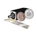
● Miniature size 42.3mmx42.3mm x17mm
● Pulse & direction stepper driver also support the standard RS232 serial command, and built-in 32bit digital chip.
● Using new control algorithms such for vibration suppression and low heat generation
● DC input voltage 12~40VDC, recommended working voltage 24VDC.
● Continuous output current 1.4A max, max peak current 2.2A.
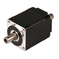
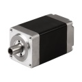
● Integrated design, mounted with NEMA17/NEMA16 stepper motor.
● Low vibration, low noise, stable operation, low motor heating.
● Any micro-step can be set .
● Protection functions such as overvoltage, undervoltage and overcurrent.
● Built-in automatic matching function of motor parameter.
● AP42 stepper driver can be assembled for NEMA17 Integrated Stepper Motors


| Pin No. | Name | Description |
| 1 | VDC | Supply voltage: 12-32VDC, Recommend DC24V |
| 2 | GND | Supply Voltage Ground: GND/0V |
| 3 | RXD | To the RX pin on user device (not for communication, set parameter only) |
| 4 | TXD | To the TX pin on user device (not for communication, set parameter only) |
| 3 | PUL | Differential PULSE signal input, Allow receiving 5V signals, Rising edge is Effective |
| 4 | PUL- | |
| 5 | DIR | Differential DIRECTION signal input, Allow receiving 5V signals, Rising edge is Effective |
| 6 | DIR- | |
| 7 | ENA | Differential ENABLE signal input, Allow receiving 5V signals, Rising edge is Effective |
| 8 | ENA- | |
| 9 | OUT | Alarm signal output, OC circuit, can receive up voltage up to 24V |
| 10 | OUT- |
If the control signal is 12V, a 1K resistor needs to be connected.
If the control signal is 24V, it is necessary to connect 2.2K resistors.
In addition to Differential wiring, AP42 Driver also supports common anode connection and common cathode connection:


Dip Switch Settings:

SW1 SW2 SW3 set Current,
SW4 SW5 SW6 Set Micro-Step,
SW8 Set direction CW/CCW.
SW9 SW10, Choose Working Mode
1. Set working current by SW1, SW2, SW3:

The default peak current at the factory is 0.5A, can be set through the serial port before sale,
The adjustable current range is any value between 0.1A and 2.2A (peak).
Set Stepper Motor's default rotation direction
SW8=on, CW
SW8=off, CCW
Note: the default rotation direction according to the wiring,
Swap wiring phase A A-(or B B-) will change the rotation direction.
Set Working Mode by SW9, SW10:
SW9 | SW10 | Working Mode |
on | on | Spontaneous pulses |
on | off | self-test |
off | on | double pulse |
off | off | Pulse & Direction |
Set Micro-Step and working speed by SW4,SW5,SW6 SW7:
Note: set SW9,SW10 for Spontaneous pulses mode, working speed will be effective when connect the 5V pulse signal.
More Information on detail, please feel free to contact me 
- Model: AP42
- Brand: Adampower
Write Review
-
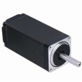 NEMA8 Stepper Motor
$35.00
NEMA8 Stepper Motor
$35.00 -
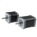
 NEMA11 Stepper Motor
$36.00
NEMA11 Stepper Motor
$36.00 -
 NEMA14 Stepper Motor
$37.00
NEMA14 Stepper Motor
$37.00 -
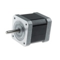
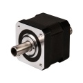
 NEMA17 Stepper Motor, 42mm Stepper Motor
$36.00
NEMA17 Stepper Motor, 42mm Stepper Motor
$36.00 -
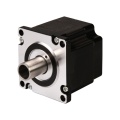
 NEMA16 Stepper Motor, 39mm Stepper Motor
$36.00
NEMA16 Stepper Motor, 39mm Stepper Motor
$36.00 -
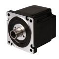
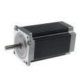 NEMA23 Stepper Motor, 57mm Stepper Motor
$39.00
NEMA23 Stepper Motor, 57mm Stepper Motor
$39.00 -
 NEMA6 Hollow Shaft Stepper Motor, 14mm Stepper Motor
$80.00
NEMA6 Hollow Shaft Stepper Motor, 14mm Stepper Motor
$80.00 -
 NEMA8 Hollow Shaft Stepper Motor, 20mm Stepper Motor
$35.00
NEMA8 Hollow Shaft Stepper Motor, 20mm Stepper Motor
$35.00 -
 NEMA11 Hollow Shaft Stepper Motor, 28mm Stepper Motor
$35.00
NEMA11 Hollow Shaft Stepper Motor, 28mm Stepper Motor
$35.00 -
 NEMA14 Hollow Shaft Stepper Motor
$36.00
NEMA14 Hollow Shaft Stepper Motor
$36.00 -
 NEMA17 Hollow Shaft Stepper Motor
$37.00
NEMA17 Hollow Shaft Stepper Motor
$37.00 -
 NEMA23 Hollow Shaft Stepper Motor
$40.00
NEMA23 Hollow Shaft Stepper Motor
$40.00 -
 NEMA34 Hollow Shaft Stepper Motor
$78.00
NEMA34 Hollow Shaft Stepper Motor
$78.00 -
 NEMA8 Stepper Ball Screw Linear Actuators
$126.00
NEMA8 Stepper Ball Screw Linear Actuators
$126.00 -
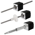 NEMA8 Stepper Lead Screw Linear Actuators
$55.00
NEMA8 Stepper Lead Screw Linear Actuators
$55.00 -
 NEMA6 Stepper Ball Screw Linear Actuators
$55.00
NEMA6 Stepper Ball Screw Linear Actuators
$55.00 -
 NEMA11 Stepper Ball Screw Linear Actuators
$55.00
NEMA11 Stepper Ball Screw Linear Actuators
$55.00 -
 NEMA14 Stepper Ball Screw Linear Actuators
$55.00
NEMA14 Stepper Ball Screw Linear Actuators
$55.00 -
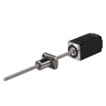
 NEMA17 Stepper Ball Screw Linear Actuators
$58.00
NEMA17 Stepper Ball Screw Linear Actuators
$58.00 -
 NEMA23 Stepper Ball Screw Linear Actuators
$58.00
NEMA23 Stepper Ball Screw Linear Actuators
$58.00


